Order Digital Reprints
Filed Under
Sign Me Up!
Sign up Digital!
Subscribe to Print!
Interested in Systems/ATUs?
Get Systems/ATUs articles, news and videos right in your inbox! Sign up now.
Systems/ATUs + Get AlertsIn previous articles we have discussed how to prepare the natural soil surface for installation of an aboveground system, whether an at-grade or mound. Last month we defined what is required of clean sand for a mound installation. This month, we will take you through the rest of the installation steps.
Only a crawler- or track-type tractor should be used for these steps. The clean sand fill should be placed around the perimeter of the scarified soil area. This way, when the fill is moved over the soil treatment area, the tractor does not always follow the same path. This helps reduce the potential for compaction.
Moving sand with care
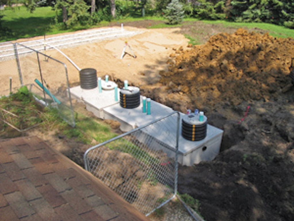
As the fill is moved over the area, at least 6 inches of sand should be kept beneath the tracks to prevent compaction of the original soil. The sand should be placed to the depth required by the design. It is easier to do this if the area is staked, indicating the levels of fill, rock and finishing material. The operator then can easily see if the fill is being placed to the proper depth.
Where the mound is to be placed on a sloping site (with a site greater than 1 percent), the upslope edge of the level absorption bed must be placed on the contour. The absorption bed is best formed by a small track-type machine with a blade – often a mini excavator. A large backhoe that can reach from the perimeter to the bed area can also be used, although reaching all areas in this way can be a problem, depending on the absorption area needed.
Traffic over the infiltrative surface of the bed should be minimized, and that includes foot traffic as well as equipment. Make sure the depth of sand over the original soil surface is at the proper depth and that the sand reaches to the top of where the distribution media will be placed.
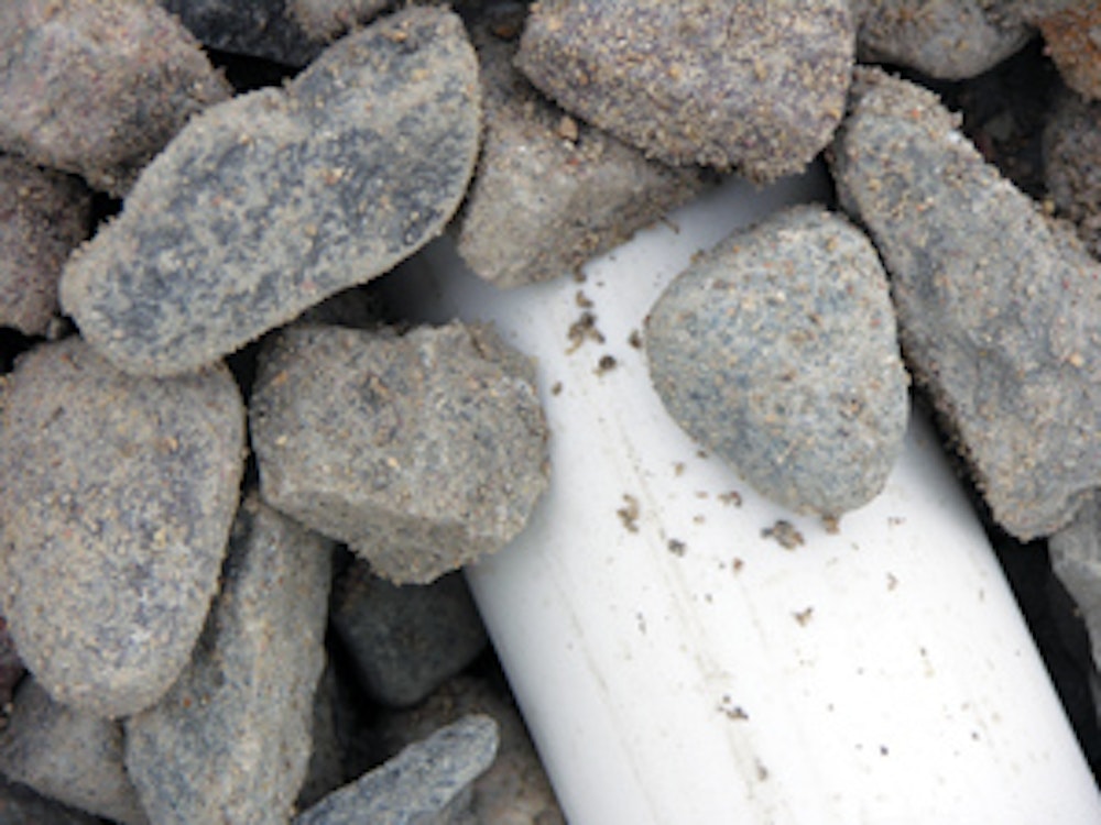
Choosing the right rock
If rock is used as the distribution media, it should be durable and decay-resistant. It should be 3/4 to 2 1/2 inches in diameter (typical drainfield rock), with no more than 5 percent by weight passing a 3/4-inch sieve and no more than 1 percent passing a No. 200 sieve.
Similarly, rock larger than 2 1/2 inches should not exceed 5 percent by weight. Limiting fines to less than 1 percent is important so that when effluent passes over the rock, fines are not washed off to accumulate at the infiltrative surface, effectively sealing the surface. Large rock is undesirable because it is hard to work with and hard to level for placement of the pressure distribution laterals. At least 9 inches of rock should be placed under the distribution piping and 2 inches above the pipe. That means the rock bed depth is just over 12 inches.
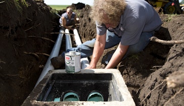
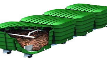
If chambers or some other alternative distribution media is used, you should hand tamp where the chambers will be located. The leaching chambers and pressure distribution piping should be installed as instructed by the manufacturer and the pressure distribution design.
When pressure distribution laterals are placed on rock, the orifices can be pointed down, or up with orifice shields. Whichever method is used, it is important to make sure all of the effluent drains out to the distribution laterals when the pump shuts off. Typically, this means drilling an orifice of the same size as the other orifices three-fourths of the way up the end cap to allow air to flow into the pipe when the pump shuts off.
Often, we see at least two orifices pointing up instead of down in a distribution lateral to provide for pipe drainage. This gives an added measure of assurance that if one of the holes gets plugged, the pipe will still drain.
When using rock, it must be covered with a durable, nonwoven geotextile fabric strong enough not to rupture during installation. In addition, the fabric must permit the passage of water without allowing the soil backfill to filter through to the absorption bed.
Providing for inspection
Most permitting authorities require the placement of inspection ports. Even if they do not in your area, you should include inspection ports anyway. They enable maintenance personnel to evaluate how the system is working in the future.
Inspection ports extend from the infiltrative surface to a point at or above finished grade. The portion of the pipe below the distribution pipe is slotted, while the portion above the distribution pipe is solid. The inspection port can be placed in a valve box for protection. Alternatively the pipe can be cut off at grade and capped.
If a slip cap is used, it must be slotted to facilitate removal easier and to ensure that the inspection pipe does not come out when the cap is taken off. The inspection port should also be secured using rebar, a toilet flange or a pipe tee at the infiltrative surface to prevent unintended removal. For chambers, the inspection ports are attached; for other alternative products, follow the manufacturer’s requirements.
Creating the slopes
The final aspect of the installation is to cover the mound. Sandy loam soil should be placed over the absorption bed with a 10:1 slope from the center of the media. This means the material is crowned 12 inches in the center and feathers out to a 6-inch depth at the edges of a 10-foot-wide rock bed.
The purpose of the crown in the center is to allow the mound to shed excess water off the top. The reason for specifying sandy loam is to avoid compaction of the cover material, which would limit the movement of water vapor and air through the material. Sandy loam provides pore space so that water and air can move freely.
At least six inches of the cover material should be topsoil borrow suitable for growing vegetation. In arid areas, the entire 12 inches should be sandy loam, and the mound should be protected from erosion using decorative rock or desert landscaping materials. Do not plant bushes or shrubs over the top of the mound.
Side slopes of 4:1 (four feet horizontal to one foot vertical) or lower are suggested. The gentle slope allows for easier mowing and vegetation control. If the area is limited, a 3:1 side slope can be used, but nothing steeper.
Next month we will take a closer look at the pressure distribution system.