Order Digital Reprints
Filed Under
Sign Me Up!
Sign up Digital!
Subscribe to Print!
Interested in Distribution?
Get Distribution articles, news and videos right in your inbox! Sign up now.
Distribution + Get Alerts
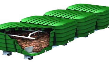
For any aboveground system to operate correctly, a pressure distribution system is required. Any such system has four interdependent components: a pump tank and pump, pump controls, pipes that deliver
effluent, and orifices that discharge effluent into the treatment area.
For many years the pump made pressure distribution systems alternative or advanced technologies. Now, pressure distribution is used in subsurface trenches and beds, aboveground systems, and advanced media filter systems. Because the use of all these systems is increasing, installers need to understand where to apply pressure distribution, how the components work together, and the keys to installing the systems properly. Pressure distribution is used:
To achieve uniform application for better treatment
To lift effluent to better soil
To avoid contamination of groundwater beneath excessively permeable soils
To improve treatment performance and extend the life of the soil treatment unit or other component
To reduce potential for seepage on slopes
To distribute effluent to aboveground systems
To disperse effluent evenly for larger drainfield systems
Evening the flow
The purpose of pressure distribution is to spread the daily flow out over the entire infiltrative surface of the soil treatment area, over the entire day.
The goal is to have each square foot of bottom area receive the same amount during each dose, and at a rate less than the saturated hydraulic conductivity of the soil.
Pressure distribution substitutes for the biomat in gravity systems. The pump controlling the application can be installed to provide the doses either on demand or through a timer. Treatment is promoted by maintaining vertical unsaturated flow, which maintains an aerobic, oxygen-rich environment in the soil or media.
Another benefit of pressure distribution is that it ensures resting periods between applications, allowing the soil or the media to recover. Designs should allow for a number of resting periods. Typically, pressure distribution systems are designed with four dosing and resting periods per day.
Equally spaced applications allow resting between doses and more uniform application, resulting in more consistent oxygen transfer and better treatment potential. A timer can further assist in spreading out the application of effluent. Demand dosing, on the other hand, turns the pump on whenever sufficient effluent is available.
Setting the dose
The most often discussed disadvantage of pressure distribution is that it needs a pump, pump tank, controls and an alarm. This means the owner has to pay for those added components as well as for electricity.
Another issue is that the distribution laterals are typically small-
diameter pipe with small orifices that must be kept clear for the system to dis-
tribute effluent evenly. Septic tank effluent inevitably contains some solids that can plug the system. Effluent screens, which are now usually required, limit the size of solids that enter the pump tank. Maintenance of the septic tank and distribution system is critical for long-term performance.
The distribution piping system includes supply pipe that carries effluent from the pump tank to the pressure distribution system and laterals, which actually distribute the effluent. The volume necessary to fill the pipe, which is the amount of effluent needed to charge the system before even distribution occurs, is an important variable.
The dose volume (DV) must be at least five times the amount needed to pressurize the system. In cold climates, the volume in the pipe needs to drain back to the pump tank when the pump turns off. Drainback is necessary to prevent freeze-ups. However, if the drainback volume is too large, the system becomes less efficient, because the pump must move a significant amount of effluent more than once.
Choosing and sizing pipe
The size and kind of supply piping determine friction loss, which affects the pressure requirement. Larger-diameter pipe has less friction loss and thus requires less total dynamic head, possibly allowing for a smaller pump. On the other hand, larger piping increases material cost for the system. The supply pipe diameter depends on the system flow rate. The pipe should be selected so as to achieve low headloss at the given flow rate.
The headloss also affects the sizing of the pump. After the main diameter is selected, compare it with the chosen manifold diameter. If the manifold is smaller than the supply pipe, the diameter of the manifold should be increased to match the supply pipe.
The supply line for pump systems must be properly bedded, and the connection between the discharge assembly and the supply line must be secure and stable. The supply line must be appropriately sized, and the pump capacity must be considered if changes are made.
The manifold connects the laterals and distributes the effluent to each lateral. Manifolds and supply pipes are usually PVC pipe with appropriate L or T fittings. The manifold pipe should be connected to the supply pipe from the pump and sloped toward the supply pipe. The manifold should be the same diameter as the supply pipe. The size and the position of the manifold and main will vary for each pressure distribution system.
Configuring the manifold
Depending on the site conditions and the design of the system, the manifold may be run along one end or down the center of the distribution system. The benefit of a center manifold is that it allows more orifices per lateral while maintaining the required minimum friction loss. The manifold must be installed level. If it is not level, effluent will flow by gravity to laterals at the lowest elevations during the filling and draining stages of the dosing cycle. Use proper bedding materials and techniques to ensure a stable installation.
The size of the taps or openings to the laterals affects the system flow. For a long manifold on a level site, the taps should be spaced to correspond with the lateral spacing, whether the manifold serves a series of laterals in a mound bed or a set of shallow, narrow, belowground trenches. This eliminates the friction loss that goes with the use of additional elbows to make the connection.
For Schedule 40 pipe, the laterals should be attached using reducing tees and joined to the pipe with appropriate adhesives. All burrs from drilling in the laterals should be removed. It is a good idea to flush the distribution network with clean water through the cleanouts to remove any debris. Next month we will focus on design and installation of the laterals in the pressure distribution network. O