Order Digital Reprints
Filed Under
Sign Me Up!
Sign up Digital!
Subscribe to Print!
Interested in Systems/ATUs?
Get Systems/ATUs articles, news and videos right in your inbox! Sign up now.
Systems/ATUs + Get AlertsLast month we looked at preliminary information obtained in a site evaluation and why it is important for an installer to understand the information. Installers may question why they need to know about soils and landscape information. This is another topic we covered extensively at the Installer 2 class at this year’s Pumper & Cleaner Environmental Expo International. As we have discussed in numerous columns, having this knowledge will save installers and the designer from making mistakes that result in time-consuming discussions with the homeowner, defending lawsuits and having to replace the system at their cost.
As we travel around the country, regulators, installers, inspectors and service providers most often explain that systems fail or do not perform properly because initial soils information is wrong, leading to poor designs and poor installations.
SIZING TABLES ARE THE NEW MEASURE
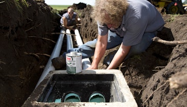
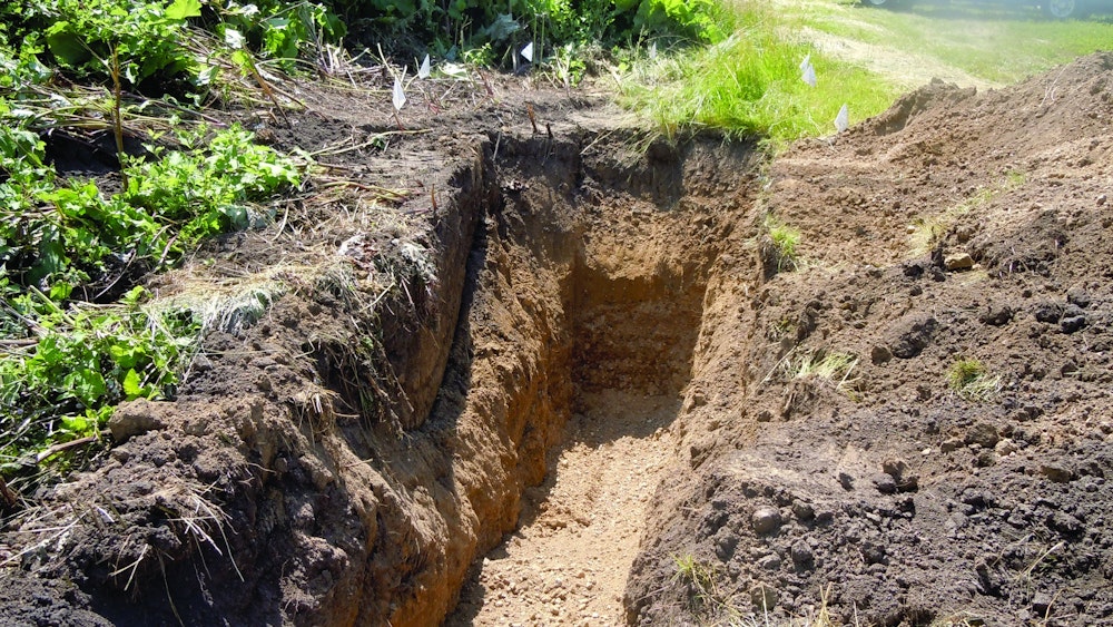
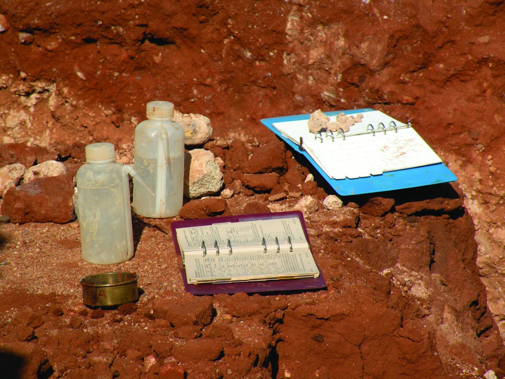
More states are adopting into their codes soil sizing tables that designate loading rates for septic tank effluent to soils on the basis of soil texture, structure and consistence. These tables have supplanted percolation tests to determine how large the system should be. This has caused a shift in how the site soil evaluation is conducted. In the past, the most common way to collect and evaluate soil samples was using a boring or probe device. Whether it is a push probe or a bucket auger, the sample is disturbed during the process, making it difficult to accurately determine soil structure and the depth of characteristics changes in the sample. The preferred method is to excavate a soil pit and get a close-up view of the entire soil profile.
When the pit is excavated – or in the case of an installer, when the trench or hole for the septic tank is excavated – the visual impression should be of a series of layers. The soil science term for these layers is “horizons” and the sum of all of the layers is termed the soil profile. During the soil evaluation piece, each of these horizons is described for color, texture and structure. In undisturbed soils, there will be at least three distinct sets of horizons. In soil science terminology, these are labeled A, B, and C horizons. The general interpretation of these is A is topsoil, B is subsoil and C is the original parent material.
The proper way to begin the evaluation is to work from the bottom up to provide the description. Similarly, during the excavation, the installer should look at the bottom to identify if there are any obvious limiting conditions that affect the depth of the system. The two primary examples would be the occurrence of bedrock or freestanding water. During excavation, an installer can often identify potential problems with soil permeability, such as dense layers that hard to dig through.
STOP AND RE-EVALUATE
Most codes set separation distances from these subsurface limiting conditions to ensure unsaturated soil for treatment of septic tank effluent. Installers should know their state and local requirements. If any of these conditions are encountered while excavating the system closer to where effluent will enter the soil, work should stop and the designer and/or site evaluator and local regulatory authority should be contacted before installation proceeds.
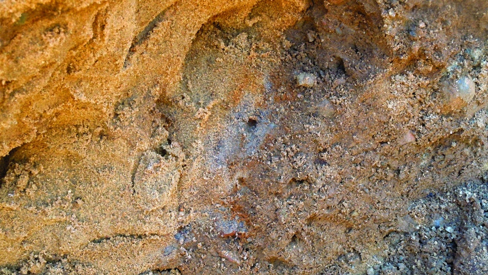
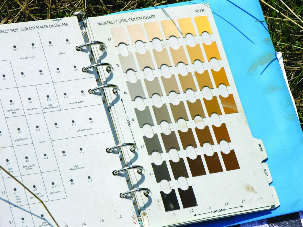
During the description of the soil profile, color is the most easily recognized change in characteristics that define the soil horizons. Important characteristics can be inferred from soil color. Well-drained soils have uniform bright colors. Soils with a fluctuating water table have a mottled pattern of gray, yellow and/or orange colors. These fluctuating water tables are often seasonal, and from a design and site evaluation standpoint are treated the same as permanent or regional water tables. Distance from the point the effluent enters the soil to the first evidence of the gray and red mottled appearance is the same.
An example of how this might impact the installation or change the kind of system installed is as follows: The site evaluator/designer has indicated that to use gravity distribution to the soil treatment trenches, the trench needs to be excavated to a depth of 3 feet below the land surface. This depth allows the sewage to flow by gravity from the house through the septic tank and into the drop or distribution box to the trenches. In Minnesota, we have a required separation distance of 3 feet. This means the installer should see no evidence of limiting layers to a depth of 6 feet to allow this installation.
MAINTAIN PROPER SEPARATION
As the installer excavates for the septic tank, soil color indicates the presence of seasonally saturated conditions at a depth of 5 feet. To maintain the separation distance the maximum excavation is 2 feet. The designer should be consulted and an evaluation made as to whether the required drop in elevation can be maintained. If not, the entire system design will need to be changed. The installer should be able to make this evaluation in the field, working off a benchmark elevation that either the designer or the installer has established.
Unfortunately, way too many installations have taken place without the proper separation distance being maintained. This leads to poor system performance and premature failure. The entire industry suffers when this happens and it could be prevented by the proper analysis of soil color.
In coming articles, we will take a closer look at texture and structure as ways to determine the soil sizing factors.