Interested in Systems/ATUs?
Get Systems/ATUs articles, news and videos right in your inbox! Sign up now.
Systems/ATUs + Get AlertsIt is easiest to design pressure distribution laterals when they are at the same elevation, which is usually the case for mound and at-grade systems. If the site is such that the laterals will be at different elevations there are additional concerns. For this discussion I will concentrate on design for laterals at the same elevation.
Pressure distribution laterals usually consist of small-diameter pipe, typically 2 inches or less. The piping and fittings should be Schedule 40 PVC. Fittings and pipe must be able to withstand pressures of 40 pounds per square inch. To provide equal distribution, the orifices should be spaced no more than 3 feet apart and spacing them closer provides better distribution. There should be a method to introduce air into the pipe so the pipes completely drain when the pump turns off. This can be an air release valve or an orifice higher in elevation at the end of the distribution lateral so air enters when the pump shuts off and the effluent in the pipe drops out into the trench or bed.
Pipe diameter, orifice diameter and orifice spacing must be determined for each pressure distribution system. Each system is unique, so the design of another system cannot be applied. A designer has to balance the diameter of the pipe and the size and number of orifices to provide the necessary lateral length to maintain equal distribution across the entire area. The larger the orifice size, the greater the flow the pump has to deliver. Larger orifices result in fewer orifices and allow shorter lateral lengths to provide equal distribution. Smaller orifices have smaller flow requirements which can result in smaller pumps and longer lateral lengths. However, the smaller orifices are more prone to plugging which can result in the need for frequent cleaning. This means that providing access and clean-outs for the laterals is necessary.
For equal distribution, the discharge from each orifice needs to be within 10 percent of the others. Another option would be to actually calculate the friction loss in the lateral assuming for 1/4-inch orifices. The operating pressure is 1 foot of head for residences and 2 feet of head for 1/8-inch-diameter orifices.
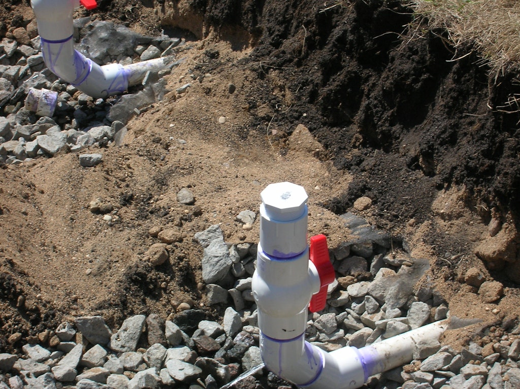
Clean-outs for the laterals should be accessible from the surface and located at the distal end of the lateral. They should be contained in a valve or similar box large enough so that they can be accessed and worked on. This includes the ability to flush the laterals to remove solids and unplug the orifices. They should have threaded or removable caps that allow for cleaning and monitoring the lateral pressure or squirt height. The most convenient layout is to use a sweep 90-degree elbow. Two 45-degree elbows can also be used for the same effect.
About the Author
Jim Anderson is connected with the University of Minnesota onsite wastewater treatment education program, is an emeritus professor in the university’s Department of Soil Water and Climate, and education coordinator for the National Association of Wastewater Technicians. Send him questions about septic system maintenance and operation by email to kim.peterson@colepublishing.com.
This article is part of a series:
- Why Use Pressure Distribution?
- What You Need to Know About Dosing Tanks
- How to Select the Best Pump for a Pressure Distribution System
- Here’s Your Supply Line and Manifold Master Class
- Tips for Laying Out Your Laterals