An architect designed a strip mall in St. Augusta, Minn., but when the developers presented the preliminary plans to installer Steve Voigt of Steve’s Excavating Inc. in St. Cloud, he spotted a serious flaw. Only 2,500 square feet was allotted for an onsite system that would treat public restrooms, eight businesses, and a 125-seat restaurant.
Voigt recommended designer Tim Haeg of Watab Inc. in Saint Joseph to save the project. Insufficient room for any onsite system forced the developers to eliminate three stores to create the necessary space. Haeg faced continued site constraints, an artificially lowered water table, only one available drainfield area with proper soils, and the knowledge that if one more store was removed, the developers couldn’t afford to build the Delux Business Center.
Haeg’s solution involved a grease interceptor, septic tank, flow equalization tank, fixed activated sludge treatment (FAST) unit, dosing tank, and a three-zone drainfield. The system, the largest of its kind in Stearns County, has set precedents for other development projects in the area.
Site conditions
In 1975, a 600-acre area in St. Augusta, a suburb south of St. Cloud, was drained to lower the water table. Later, some commercial lots were established with a filling station and mini-mart at a busy highway intersection. Soils are sandy with a percolation rate of less than one minute per inch. Agricultural fields surround the lot. The rapidly developing area has huge business growth potential.
System components
Tim and Greg Haeg and Don Fischer designed the system to handle 5,617 gpd. They oversized it by 25 percent as a safety factor. “The drainfield’s three zones allow for a rest and recovery rotation, which probably won’t be necessary, since the FAST unit should prevent a biomat from developing,” says Tim Haeg.
Although the ATU made it possible to reduce the size of the drainfield, the designers did not do so because local regulations have no performance-based reduction credit. Furthermore, with no room for another absorption bed, they couldn’t afford a system failure. The system’s major components are:
• 5,000-gallon, single-compartment concrete grease interceptor tank. All tanks made by Wieser Concrete Products Inc., Maiden Rock, Wis.
• 6,100-gallon, single-compartment septic tank with dual inlets.
• PL-525 effluent filter from Polylok Inc., Wallingford, Conn.
• 7,700-gallon, single-compartment flow equalization tank with two LE40, 4/10-hp pumps from Liberty Pumps, Bergen, N.Y.
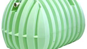
• 9,000-gallon pretreatment tank with 9.0 HighStrength FAST aerobic treatment unit from Bio-Microbics Inc., Shawnee, Kan.
• 2,000-gallon dosing tank with 36-inch square hatches and three LE100, 1-hp, high-head pumps from Liberty Pumps.
• 468 Quick4 Standard chambers from Infiltrator Systems Inc., Old Saybrook, Conn., set 65 inches on center in three, 1,872-square-foot zones.
• 24 valve boxes
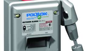
• Custom control panel with telemetry from Alderon Indus-tries Inc., Hawley, Minn.
Granite Water Works of Waite Park, Minn., supplied all components except the tanks.
System operation
Waste from the kitchens flows through a 4-inch Schedule 40 PVC pipe to the grease interceptor. Sewage from the stores and three public restrooms flows through a 6-inch Schedule 40 PVC pipe to the septic tank. A 4-inch PVC pipe connects the grease interceptor to the septic tank.
Effluent gravity-flows through a 4-inch line to the equalization tank, where pumps send 400 gallons per cycle to the FAST unit through two 2-inch pipes. The pumps run eight minutes every four hours (Haeg is adjusting the cycles as hydraulic flows stabilize).
The designers chose the FAST system because FOG was an issue. The unit is an economical way to reduce BOD, and it requires little maintenance. Since the site is not required to achieve a specific nitrogen standard, effluent from the ATU gravity-flows through a 4-inch pipe to the dosing tank.
Pumps send 400 gallons every four hours to the drainfield. “Using three pumps instead of two allowed us to reduce their size and the gallons-per-minute requirements,” says Tim Haeg. “We also avoided splitter valves, because they can freeze in Minnesota.” A backfall of 40 inches drains liquid back to the dosing tank when the pumps stop.
Each pump’s 2-inch supply line connects to a manifold feeding one zone of four trenches. A 24-inch dual wall pipe with a shutoff valve on both ends runs down the center of every trench. The valves enable Haeg to program rest and recovery cycles, and use a much smaller area of the drainfield to ward off freezing in winter. The lateral also has a flush valve at each end.
“We’re using pressure distribution because the drainfield is elevated above grade, and to achieve even hydraulic loading across the entire absorption bed,” says Haeg. “Most important, we use pressure distribution when working with effluent that won’t necessarily develop a biomat.” Haeg is switching zones quarterly until the mall has operated long enough to establish its water use habits.
Installation
Installation began with the drain-field as the tanks were manufactured. “Working with the site was easier because the water table was lowered, but it was still challenging,” says Haeg. “We had to keep in mind that a beaver damming the drainage ditch could raise the water back to its original height.”
Unable to guarantee that the water table would remain at 5 feet due to dependence on the ditch, Haeg specified soil corrections to make the site more suitable. Voigt and his 15-man crew removed 4 feet of organic topsoil from the 4,662-square-foot drainfield, replacing it with sand to maintain a consistent soil texture between the distribution media and water table.
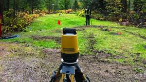
An additional 3 feet of sand was placed above grade to create a mound system. Importing the 4,500 cubic yards of material took three-and-a-half days using nine dump trucks hauling 420 loads. Voigt used a low-ground-pressure (LGP) John Deere bulldozer and a Caterpillar bulldozer to push the sand in place. A laser mounted on the latter provided the grade levels.
Haeg specified chambers for the distribution method because they were clean and light enough for the men to carry and assemble on the flat prepared site. “They snapped together, enabling us to install them in one day,” says Voigt. The drainfield was backfilled with more sand and covered with the removed topsoil.
Excavating the tank holes was the biggest challenge. The pit for the pretreatment tank was 1 foot below the water table, but the hole for the septic tank was 4 feet below it. Voigt rigged one 4-inch and three 2-inch trash pumps to hold the water at bay. He imported 100 cubic yards of sewer rock to create 12-inch deep stable bases as the pits were dewatered. “We couldn’t afford to have any settling because everything was grade minimum,” says Voigt.
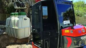
The grease interceptor tank and dosing tank were delivered and set by Wieser’s boom truck. Landwehr Construction of St. Cloud, Minn., set the remaining tanks using a 30-ton Terex crane. Property lines and the drainfield restricted the crane’s movement, and the weight of the tanks limited its reach. Conse-quently, the tanks were installed in reverse order, allowing the crane more room to move.
“We set the FAST tank first, so the crane could come close enough to the pit and not tip over,” says Voigt. “Setting the deepest tank first would have parked the machine on top of the septic tank.” The bottom half of the pretreatment tank with FAST unit weighed 29,000 pounds.
The tops of tanks having less than 3 feet of cover were insulated with two layers of 2-inch foam sheets, each 4-by-8 feet. The 4-inch kitchen waste pipes received the same treatment to prevent liquid from freezing as it passed beneath the plowed parking lot in winter.
“The width of the insulation prevents lateral movement of the frost toward the pipe,” says Voigt. “We also staggered the seams when installing the second layer of foam to create a frost break.” The three shallow drainfield dosing lines were insulated, too.
Maintenance
Watab Inc. is responsible for maintaining the system. Haeg will inspect the grease interceptor monthly until flows are established, then quarterly thereafter. He also checks the drainfield for ponding and adjusts the pump and control panel settings to match the facility’s actual flow. Although not required to sample the effluent in the dosing tank, Haeg does so quarterly to guarantee that the FAST system is producing the required treatment. Once a long-term pattern is established, sampling can occur annually.
Continue reading for free