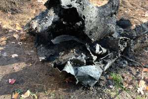
The decades-old septic system had failed at a property on Crescent Lake near the city of Rhinelander in north-central Wisconsin.
Effluent from a steel septic tank was pumped uphill to a stone bed that had become root-bound and no longer allowed the water to percolate. As a result, there were backups into the three-bedroom seasonal cottage if the owners used large volumes of water, such as for showers. The steel tank had corroded so that wastewater was able to leak into the groundwater and ultimately contribute to pollution in the 616-acre lake.
The property owner turned to A-1 Septic Service & Installation to create a new onsite system. Owner Tom Arts called on Dale Schlieve of Conscientious Effective Consulting to design a solution for the challenging property.
Schlieve collaborated with Mark Prevost, fluid handling technical service manager with First Supply of Eau Claire, Wisconsin, on a system with a drainfield using compact treatment modules. The configuration made it possible to install a drainfield roughly half the conventional size required to treat the wastewater flow from the cottage.
The pie-shaped lot of slightly less than one acre, with 175 feet of lake frontage, had significant areas of impermeable blue clay, unsuitable for a conventional drainfield, in the level area near the cabin. This made it necessary to locate the drainfield on higher ground farther from the lake, between the slanting driveway and the town road.
Schlieve designed the system to handle 450 gpd. Major components are:
The soil conditions and small space available on the site dictated the choice of the treatment modules. Schlieve conducted a soil test to identify the depth at which the drainfield soils had a long-term acceptance rate of 1.6 g/ft2 as required to allow the smaller drainfield.
“On many lake lots, there is just no area,” Arts observes. “The Eljen material is another tool in the box that sometimes gives us enough space to get a system in.” The drainfield is 33 feet long and 10 feet wide. Arts notes that a conventional drainfield likely would have been 65 feet long by 9 feet wide.
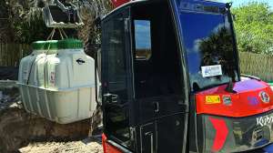
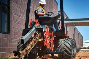
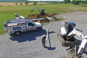
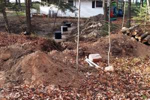
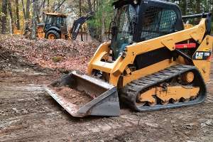
The property owner wished to preserve as many trees as possible; even with judicious cutting, some 20 trees had to be removed to make space for the system. The excavations were done with a John Deere 410 rubber-tired backhoe and backfilled with a Caterpillar compact track loader.
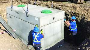
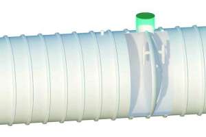
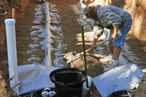
The A-1 team removed the old septic tank and pump tank. In the new tank excavation they encountered extremely heavy clay soil with extensive mottling but no significant water. Nevertheless they used “wet prep” tanks impregnated with a chemical that will mend and seal cracks that may eventually appear.
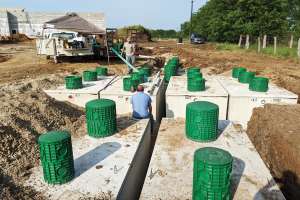
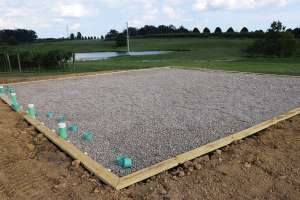
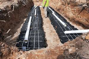
The drainfield area was excavated to one foot below the specified system elevation; that foot was then filled with ASTM C33 mound sand and leveled manually. There must be at least two feet of suitable soil beneath the sand layer. Two rows of B43 GSF modules, two feet apart, were then placed on the sand, eight modules per row. Next, 4-inch perforated pipe was laid on top of modules.
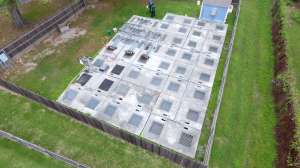
One foot of sand was placed along the sides of the module rows and six inches of sand at each end. The entire installation was then covered with high-tensile fabric that allows air and water to penetrate but excludes sand that could clog the treatment units. The system was then backfilled with ASTM 33 sand followed by 12 inches of clean and porous fill.
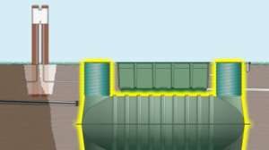
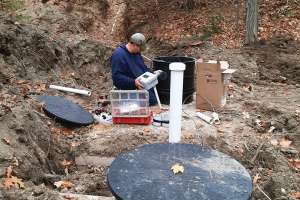
Wastewater from the cottage flows by gravity to the septic tank; effluent discharges to the pump tank where the level is regulated by dual floats. The upper float serves as a failsafe, triggering an alarm inside the cottage in case of high water indicating a pump failure.
The pump sends effluent through a 2-inch force main up to the drainfield. The section of force main under the driveway is encased by 2 inches of solid insulation to prevent freezing where the soil has been compacted by traffic.
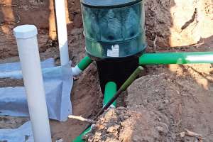
About 2 feet ahead of the distribution box at the head of the drainfield, the force main diameter widens to 4 inches to slow the flow. The water then makes a 90-degree bend down into the distribution box, which sends wastewater equally via the perforated pipe to the two rows of treatment modules. At the end of each pipe is an inspection port.
Each GSF module is made up of geotextile fabric and a plastic core; the two work together to provide vertical surface area and oxygen transfer for treatment. The secondary-treated effluent leaving the GSF modules is further treated in the soil. This cleaner effluent enables an increase in the soil’s long-term acceptance rate, leading to a reduction in drainfield size.
Maintenance is the same as for a conventional in-ground except that the pump amperage needs to be checked periodically to make sure it is not wearing or starting to clog. The septic tank needs to be pumped every three years and the effluent filter cleaned every year. The distribution box should be checked to make sure the flow remains evenly distributed to the rows of treatment modules, or speed levelers can be installed to equalize the flow.
Continue reading for free