In a past article, I wrote about the challenges associated with gravity distribution. One of the options mentioned was using a siphon, but the research available indicated siphons commonly trickle without frequent maintenance, reducing the efficiency of these devices. Siphon technology has evolved since the research was done in the 1980s. Designers and installers should consider using a siphon, which can also be used provided the succeeding component (typically a soil treatment area) is at a lower elevation. If designed, installed and serviced appropriately, the effluent distribution will be dosed in surges, with resting being doses and evenly across the component.
Common applications for siphons include:
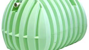
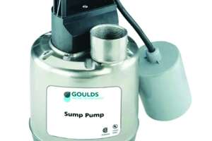
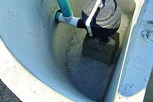
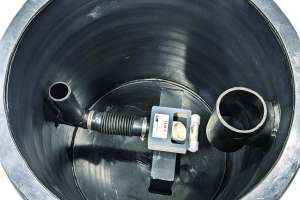
A siphon typically consists of a dosing chamber (it cannot be placed in a septic tank), a siphon and a discharge pipe. Siphons should be placed in a vessel or chamber downgradient from the septic tank, and the effluent should be filtered before being introduced to that chamber. They can be used in demand dose systems, but not when time dosing is required.
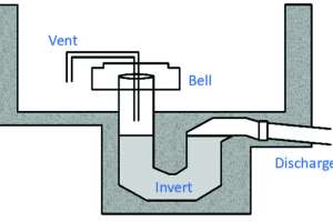
As liquid fills the dosing tank, the liquid level in the tank and siphon rise simultaneously. The siphon is vented to the atmosphere through the vent.
This rise continues until the liquid reaches the vent pipe’s open side, creating an air seal.
As the liquid rises in the dosing tank, it rises much slower in the bell. The pressure of the water pushes the air at the top of the bell and in the vent pipe toward the invert of the trap.
When the effluent reaches the dosing tank’s high-water line, the air volume is forced around the invert of the trap and out of the discharge pipe. When this air escapes, it releases the back pressure within the siphon; the liquid in the bell will rush up, fill the trap and start the siphon action.
The liquid is drawn out until the liquid in the dosing tank reaches the bottom of the bell.
The siphon only functions if the pretreatment or dispersal component receiving the dosed flow distribution is at a lower elevation than the siphon discharge, typically by several feet. The amount of fall required will relate to the length of the supply pipe and the needed head at the discharge point. The drawdown of the siphon (determined by the manufacturer) multiplied by the volume per vertical inch of the dose tank, determines the dose volume the siphon delivers. The dimensions of the dosing tank are critical and should not be altered during installation without consulting the designer.
Siphons do not require a discharge assembly like that included with pump systems. Instead, the discharge pipe delivers the dose to the next component at a lower elevation. Siphons have discharge rates ranging from 25 to over 100 gallons per minute.
Although siphons are very reliable, they occasionally can go into trickling mode. Siphon trickling typically starts when the siphon tank receives a large dose of influent while the siphon is at the end of a dose. This is a matter of bad timing. As the liquid level is close to the bell bottom, the siphon takes a gulp of air as the liquid rises, but there is not enough air to break the siphon. The dose volume is not completely delivered, and a small amount of effluent continuously trickles from the tank. As with all components, access to this unit is critical to re-establish the siphon action by injecting air under the bell.
Digital and mechanical cycle counters are recommended to help monitor flow. The counter enables the service provider to calculate the average flow to the system during operation and maintenance. The counter can also be used to troubleshoot the system for leaks, trickling or to determine if the system is hydraulically overloaded. They are typically battery-operated since electricity is not commonly available. A visual high-water alarm is also recommended on siphon systems.
There are numerous brands of siphons on the market. Finding one locally available is always a great place to start, as the supply company can assist in designing and installing them.
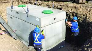
The flow rate of the siphon is an important parameter that must be determined in the design. When installing a siphon, ensure it can meet the required flow in gallons per minute (gpm). This average is calculated from the maximum rate (when the siphon just started) and the minimum rate (at the end of a cycle). The siphon and components must be easily reachable from the opening. The siphon should be directly under the lid of the tank access riser.
The discharge pipe for a siphon must be properly bedded and connected to the outlet of the siphon using appropriate fittings. The diameter of the discharge pipe should be at least as large as the diameter of the siphon trap for a minimum distance of 10 feet past the overflow pipe. If it is important to maintain a flow rate as high, the discharge piping should be one size larger than the siphon to reduce friction losses (e.g., use 6-inch discharge piping with a 4-inch siphon). However, if the goal is to pressurize an LPD, the 6-inch pipe may be inappropriate. Consult the manufacturer for specific information or before making changes.
The discharge pipe from a siphon must not run uphill. It must run downhill with typical slopes of
1. Pipe diameter of 2 ½ inches or smaller, sloped at 1/4 inch per foot
2. Pipe diameter of 3 to 6 inches, sloped at 1/8 inch per foot
3. Pipe diameter of 8 inches or larger, sloped at 1/16 inch per foot
As with supply lines, an air-release valve should be included at the highest point if variations in elevation from the siphon tank to the next component might result in air becoming trapped in the line. The discharge pipe should be vented back into the dosing tank through an overflow pipe.
The siphon must be primed when installed by filling the tank with water. Testing should be done to confirm that the siphon operates as designed.
A Flout can be used in similar applications to a siphon, but is more like a tipping bucket floating in a tank. The name brand Flout stands for “floating outlet.” The device starts at the bottom of the dosing chamber empty. As the effluent from the septic tank fills the dosing chamber, the Flout is empty, buoyant and floats on the surface. Flexible connectors allow the device to rise.
There is an opening in the upper side of the vessel with an attached ballast weight. A length of pipe extends far into the vessel, through the side, and attaches to a special flexible connector the same diameter as the pipe. The flexible connector acts as a hinge, allowing the vessel to float higher as the dosing chamber fills. The other end of the connector is connected to the outlet, usually via a tee fitting with a vent extending above the maximum liquid level.
When the vessel can float no higher, effluent spills into it, forcing it to sink to the floor, allowing effluent to flow through the outlet. When the liquid level drops to the top of the vessel, the flow stops when the vessel drains and re-floats in the remaining liquid. There are many options available for designing this dosing mechanism.
Due to the floating nature of this device, having an effluent filter prior is recommended, and the septic tank and dosing chamber will need regular maintenance. The bottom side can get scummy, and then you risk it getting stuck on the surface. In some applications, it may not create enough force to scrub LPP lines, and line cleaning may be needed.
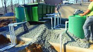
These non-electricity-using dosing options have many of the benefits of a pump system. If the site offers you the option to use natural elevations to create uniform distribution, it should be considered. These devices hold a dose, allowing for resting between dosing. When dosing to a distribution box, they will more uniformly dose the system due to the larger volume, and in pressure applications, they can achieve pressurized application over the STA.
Continue reading for free