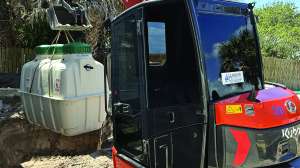
I received a call from a customer in panic mode. They just had their pump replaced and it wasn’t working — even with the brand-new pump, they were still backing up. The plumber swore up one side and down the other that he replaced the pump with the exact same pump so “it should work.”
I did what I always do: called the county and asked for a copy of the information pertaining to the onsite system, and made sure they included the inspection report. While waiting for the county documents, I received from the customer the exact make and model of the pump that was installed and I looked up the pump curve online. After receiving the county information, there was immediately a ‘smoking gun’ answer on the pump curve itself. The county info said vertical lift was 21 feet. For the pump that was installed, the entire TDH curve did not even go to 20 feet; the TDH on the curve ended at about 17 feet of head. The inground system was straight up a hill 21 feet above the pump, but the pump curve clearly showed that the pump was never designed to pump that high — it couldn’t and it wasn’t. The pump installed could not physically lift the water as high as was needed, and a simple check with the pump curve would have warned that plumber not to bother installing that pump.
Never install a pump in an onsite system without consulting a pump curve. Sounds pretty straightforward, yet almost every week I replace pumps that failed (or simply did not work) because they were never sized properly using a pump curve. I always ask the county for the inspection report, and have found several pumps that were inspected at the time of system install that never met the curve properly; they were the wrong pump upon installation.
To properly size a pump so that it lasts as long as possible for the paying customer, the installer must know two things: gallons per minute and total dynamic head. Let’s break each of those down.
TDH
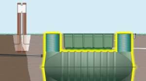
TDH stands for total dynamic head. Total dynamic head is critical to the proper functioning and longevity of any pump. What you need to know for TDH is: vertical elevation difference between the pump and the highest elevation you are pumping to (lateral), and friction loss in the force main (explained below). In the case of a pressurized system you will also need to know your minimum distal head pressure and in some cases add a number for fittings, which we will discuss below.
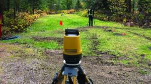
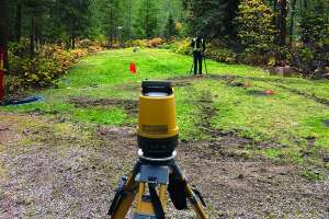
On the pump curve the TDH is in most cases the vertical line on the left. To determine TDH you need to know the elevation difference between the pump and the highest point you are pumping to. So if you shoot that with a laser level (or GPS, or whatever technology you use to determine elevations) and let’s say for example that we have 10 feet of vertical difference between the bottom of the pump and the lateral elevation you are pumping to. Please note that engineers reading this might have a slight quibble here and say the vertical elevation difference is from top of water and, yes, that is correct; but the difference in an onsite system pump and top of water is negligible, and in the onsite industry, it’s used as a method of standardizing this variable.
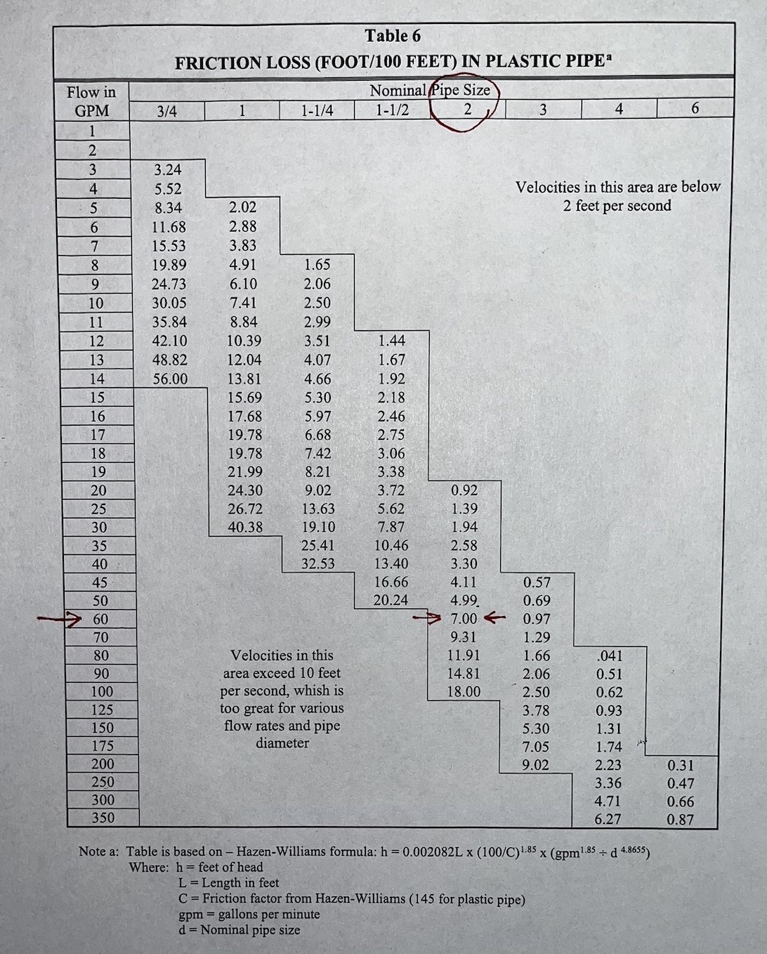
Friction loss: Part of the TDH is friction loss. We need to know the size (diameter) and length of the force main. And this example assumes a PVC force main, as different materials will have different friction losses. For our example we will use a 2-inch force main that is 60 feet long. And remember we have 10 feet of vertical lift. Friction loss can be determined based on different mathematical formulas that include the Hazen-Williams formula or the Darcy Weisbach equation but lucky for us many states design manuals (and other engineering manuals) that include charts that help to determine friction loss. Friction loss is the loss of energy that the water you are pumping encounters due to the different resistance in different pipe materials. Friction loss changes with gallons per minute and diameter of pipe as well. For our example let’s say we are pumping 60 gallons per minute.
If you look at the friction loss chart at 60 gallons and go over to the 2 inch column, the friction loss is 7.00 in 100 feet of pipe. But we only have 60 feet of pipe. So 0.6 x 7.00 = 4.2. Our friction loss in 60 feet of 2 inch pipe at 60 gpm is 4.2.
If this were a system where you were merely pumping uphill to a gravity system, then the TDH is the 10 feet of lift plus the 4.2 friction loss. Our TDH is 14.2. If this were a pressure system, we would add the minimum distal pressure required (the pressure required at the far end of the system) and in some cases additional pressure will be added for friction loss in fittings such as 90 degree ells.
So we take our 14.2 TDH on the left side of the chart, go across at 14.2 until you come up with the pump that will give you the 60 gpm or more, but not less. If you look at our example chart, it would be the second pump we come to, not the first, because the first would not get us our 60 gpm.

Gallons per minute
Gallons per minute required, or gpm, is based on several things.
Pumping to a nonpressurized (i.e. gravity) system: Here in most cases you can choose what gpm you want to pump as there is not a specific requirement. But once you choose the gallons per minute, that is the number you must use when calculating the proper pump on the pump curve.
Pressurized systems: gpm is based on the minimum pressure your system requires (typically code derived). In my example I’ll use 0.25 inch size orifices. My design manual for state code purposes says that I have to maintain 2.5 feet of pressure. The chart in my design manual says that at 2.5 feet of pressure, 0.25 inch holes require 1.17 gallons per minute per orifice. Working backwards with the previous example, assume my system has a total of 51 orifices. 51 x 1.17 per orifice is 59.67 gallons per minute, which is how I came up with my 60 gpm requirement.

Please note that you want your pump to be as close to the center of a curve as possible. Too close to the right (low) end and the pump burns out fast because it does not have enough resistance (think pumping downhill). If the pump is too far to the left (upper) part of the curve there is too much resistance, which will also cause faster failure of the pump. Always aim for as close to the center as possible.
Each pump you might use has its own individual pump curve. There is not a one-size-fits-all pump curve.
Using the pump curve is incredibly important for the proper function and longevity of the pump you install.
The charts used in this article are from the Wisconsin Safety and Professional Services Pressure design component manual.
About the author
Todd Stair is vice president of Herr Construction, Inc., with 34 years’ experience designing, installing, repairing, replacing and evaluating septic and mound systems in southeast Wisconsin. He is the author of The Book on Septics and Mounds and a former president of the Wisconsin Onsite Water Recycling Association.
Continue reading for free