A couple remodeling a summer cottage in Hatfield, Wis., into a two-bedroom retirement home asked Rich Halverson of Halverson Plumbing in Black River Falls, Wis., to replace the holding/trash tank he had installed 10 years earlier with an onsite system.
A soil analysis on the 10-acre lot revealed that groundwater had reached the surface in spring. State code requires 3 feet of separation between the bottom of the drainfield and the seasonal high water table. When dry, the site had 36 inches of drainage.
“The water table was our stumbling block,” says Halverson. “A mound system with pretreatment would work most of the year, but I knew the state wouldn’t accept that.” Frustrated by the lack of commercial answers, Halverson designed a solution that deactivated the system during high groundwater events, yet protected the environment.
Site conditions
Soils are sandy with sandstone bedrock 3 feet below. A layer of blue clay covers the bedrock. The wooded lot is at the base of a 2-mile-long gradual slope.
System components
Halverson sized the system to handle 300 gpd. Its major components are:
• 2,000-gallon one-compartment concrete holding/trash tank made by Crest Precast, LaCrescent, Minn.
• Effluent screen, model ES1548FB, Orenco Systems Inc., Sutherlin, Ore.
• Two 4/10-hp pumps, Sta-Rite, Delavan, Wis.
• High-water alarm, SJE-Rhombus Controls, Detroit Lakes, Minn.
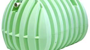
• 500-gallon Multi-Flo aerobic treatment unit, Consolidated Treatment Systems Inc., Franklin, Ohio.
• 30- by 60-inch fiberglass pump chamber, Topp Industries Inc., Rochester, Ind.
• Control panel, MF-080D4BR, Consolidated Treatment Systems Inc.
• EZflow geosynthetic aggregate drainage tube, Ring Industrial Group, Oakland, Tenn.
• Three WL15 water-level dataloggers, Global Water Instrumentation Inc., Gold River, Calif.
System operation
Wastewater flows through a 4-inch PVC lateral into the holding tank. A pump inside an effluent screen sends 20 gallons every 30 minutes to the suspended-growth/ fixed-film (ATU). The unit sits higher than the holding tank, enabling 17 gallons to drain back, preventing liquid from freezing in the 2-inch PVC pipe.
An aerator near the bottom of the ATU draws air into the reactor chamber. Mixed with wastewater, the air sustains bacteria that consume organic materials. Suspended in the tank are 30 filter socks, each with 100-micron filtration, that prevent solids from reaching the drainfield. The process reduces BOD and TSS to 5 mg/l.
Treated effluent gravity flows through a 4-inch PVC pipe to the pump chamber. The 0.4-hp effluent pump, with on-demand dosing, sends 50 gallons to the mound. Its 3- by 75-foot disposal bed has a 1 1/2-inch drainage tube down the center. Effluent, flowing out 60 1/8-inch holes spaced 15 inches apart seeps through the tube’s surrounding aggregate, trickles through the mound sand, and enters the environment.
Installation
Plan approval began as a variance to put a system on a site with less than 6 inches of soil. However, the design set a precedent and was sent to the state’s individual site design team for review. Two months later, Halverson had his approval.
The homeowner cut down the necessary trees but left the numerous stumps flush with the ground. Ripping them out would create channels for the groundwater.
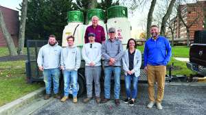
Halverson’s crew remodeled the holding tank by installing the pump inside an effluent screen, then set the ATU and pump chamber. They used 10 bags of concrete mix to encase the antifloat foot at the bottom of the chamber.
The pump chamber has limited reserve capacity. “We didn’t want a big one shooting 200 or 300 gallons of wastewater to the mound when the system activated,” says Halverson. “Our goal was to send a small dose.”
Halverson’s solution was to drill a 4-inch hole in the pump chamber just above the activation float. Should the pump fail or during shutdown, the effluent drains into a 4-inch pipe, loops back to the house lateral, and enters the holding tank. Recirculation eliminates the need for large storage capacity and feeds the bacteria in the ATU when the system is inactive. Since no liquid reaches the mound, a high-water alarm signals when the holding tank needs pumping.
Testing performance
Building the mound required roughing up the soil and adding 15 inches of washed sand. However, the backhoe tore fibers off the roots and stumps. “We used a salad rake, a tool that attaches to the backhoe and removes vegetation,” says Halverson. After placing Type-R fiber over the drainage tube, the crew added 12 inches of sandy loam fill.
Down slope and just off the toe of the mound, Halverson sank a 3-foot-deep fiberglass riser surrounded by and seated on 12 inches of gravel. Inside is a float rod with a backward-operating float (the switch is normally closed). When groundwater rises to 10 inches of grade, the switch shuts off the system. When the water level drops to 16 inches below grade, the switch activates the system.
“The ATU gave us 12 inches of separation,” says Halverson. “Putting 15 inches of sand under the mound and shutting off the system at 10 inches gave us 25 inches. That’s 37 inches of separation, or one inch above code.”
The individual site design team required Halverson to monitor groundwater levels twice per day for a year. “The state wanted to know if we had the correct separation between the high groundwater and the base of the mound,” he says. “If the water level was higher than anticipated, we could set the shut-off float a little lower.”
Halverson selected test sites just down slope of the mound — one in the center and one toward each end — and installed a slotted 2-inch PVC pipe in a gravel pack at each location. “The water level dataloggers have a collar that fits over the pipe and prevents them from falling down,” says Halverson. “The instrument has a 9-volt battery on top and a 36-inch-long tube with a stainless steel sensor on the bottom. It’s slick.”
Halverson set the dataloggers to take a measurement every 12 hours. Twice, at six-month intervals, he visited the site and downloaded the data into his Palm Pilot. The study proved that the separation factor was correct.
The homeowners moved into the remodeled home in late spring 2006. A local septic service pumped the holding tank once in the spring of 2007 and 2008.
Maintenance
Halverson Plumbing holds the two-year renewable maintenance contract. Every six months, a technician services the ATU, cleans the filter socks, and checks the float that activates or deactivates the system.
Continue reading for free