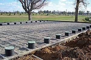
We have been looking at systems that use gravity to move the effluent. This month we complete this part of the discussion by looking at installing soil treatment trenches or beds.
Most codes we see define trenches and beds. Most recognize trenches as being no more than 36 inches wide and beds as being anything wider. Codes usually specify a maximum bed width. As always, it is important to know the requirement for your state or area. Typical bed widths are 10 to 12 feet.
It is also important to know the requirements for separation from the bottom of the trench or bed to limiting soil condition – bedrock or the water table. For this reason, some states, including our state of Minnesota, have a maximum depth of excavation of 48 inches. This helps ensure that the system is kept shallow and uses the best part of the soil profile for treatment.
When we get involved in designing gravity systems, we always use trenches. Trenches allow for better oxygen exchange under and around the system. They also have more infiltrative surface area for the same bottom area, allowing for better treatment. Having trenches also reduces the likelihood that the bottom is compacted or smeared due to traffic during installation.
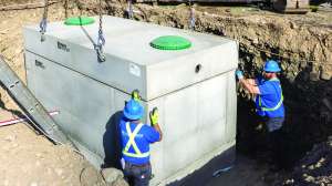
The bottom of the trench or bed should be excavated level. When a bed is excavated, it is important not to drive over the bottom. If you use a bed, you should excavate by working around the perimeter. Remember: one key to good installation is to keep the soil in its natural condition.
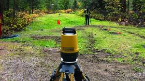
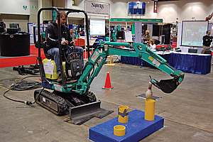
When installing trenches on sloping sites, it is even more critical than usual to identify the elevation of any limiting soil condition and to maintain the required separation. If you use a tracked backhoe, you’ll need to create a pad from which to work so that you can dig the trench level and on the contour. Check your local requirements for the maximum slope allowable. In most codes, we see a maximum of 15 percent.
Wheeled backhoes can usually be leveled using stabilizers. If the soil is deep enough, you can create a bench on the upslope side of the trench being excavated. You then place the spoil downslope to create a bench to set the equipment on to excavate the next trench. Where the soil is shallow, you may have to use a mini excavator perpendicular to the slope and use the blade to stabilize the machine.
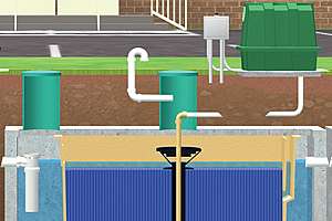
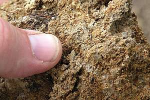
The excavations will be filled to the proper level with the selected media. In the old days, the media was always clean rock, three-fourths to 2.5 inches in size. These days, we have a number of media choices.
The trench media has five functions: distribute effluent, provide water storage area, dissipate energy, insulate, and prevent root penetration. In general, there is little treatment in the media itself – it serves primarily to maintain the trench form and distribute the effluent. We see proprietary products on the market today that claim to enhance treatment in the media – these are relatively new to the scene.
If you use rock media, take care when placing it so that you do not damage the soil infiltrative surface. In other words, don’t simply drop the rock from the bucket of the front-end loader. Work your way around the system and place the rock in smaller increments.
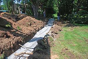
You then place the 4-inch distribution pipe level and cover it to a depth of two inches with rock. A geotextile fabric placed over the top of the trench then prevents fines from filtering through the rock and sealing the soil infiltrative surface. Finally, backfill the system to provide a minimum of six to eight inches of cover.
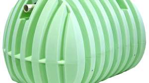
Other recognized media include chambers, gravelless pipe, and expanded polystyrene, as well as a few others. Chambers are usually constructed of high-density plastic. There are a number of such products on the market. They generally have a plastic dome with slots or orifices cut in the sides and are open on the bottom.
Gravelless pipe is a corrugated pipe, usually 12 inches in diameter. The corrugations are usually one-half to three-fourths-inch separations. The pipe also has half-inch orifices in the bottom, and they are placed at the four o’clock and eight o’clock positions. The pipe itself is wrapped in a geotextile fabric. The pipe is made to be in direct contact with the soil so that the biomat forms at the pipe/soil interface.
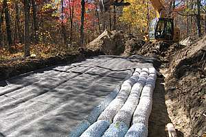
The expanded polystyrene media comes in 10-foot sections with a 4-inch corrugated pipe surrounded by the polystyrene. The material is held together with polyethylene netting. The sections can be placed in various configurations according to manufacturers’ instructions.
All these media also require level excavation. Chambers are laid in the trench and then the sidewall area is backfilled with soil and stepped in with minimal pressure. The area is then over-backfilled to allow for settling and to ensure that runoff water is diverted from the system.
The gravelless pipe is laid in the trench and backfilled with soil in small increments to ensure that the pipe does not move. The area is then backfilled and crowned for settling and runoff. A similar procedure is used for the polystyrene media.
For all products, check and follow exactly the manufacturers’ recommendations for installation. Next month we cover aboveground systems: mounds and at-grades.
Continue reading for free