Sizing a drip distribution system is based on the daily wastewater flow and the soil texture and structure. Manufacturers give a range of system sizes that are based on long-term soil acceptance rates. These values are similar to the design rates for soil treatment trenches but the area is larger since the goal of using drip distribution is to spread the effluent out evenly over time, and at the same time maximize the surface area that is in contact with the effluent.
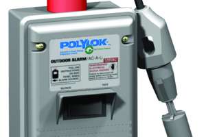
Accomplishing even distribution requires that flowmetering and time dosing be employed as part of the system. This can be done through the use of flowmeters, elapsed-time meters or cycle counters. This gives service providers the ability to determine what the actual flow is to the drip distribution field over time. Flow to different sections of the field can be altered as necessary to match conditions.
The tubing used in the dripfield must be approved for use with wastewater by the manufacturer, so using just any drip tubing is not acceptable. Tubing used to irrigate orchards or vegetable gardens may not be appropriate. Tubing is approximately 1/2 inch in diameter with an emitter incorporated into the tubing wall at specified intervals.
A dripfield has drip tubing installed along the contour to form a “run” of tubing. There can be more than one run. The runs are connected to the supply and return manifolds with flexible tubing to avoid separation due to settling or the action of being turned on and off. Individual runs are most often looped together to form a lateral. So a run is defined as one dripline along the length of the zone and when looped they form a lateral that consists of two or more runs. The layout for each zone of the system takes on the appearance of a ladder.
If the tubing has non-compensating emitters the layout of all runs needs to be level and the runs all have to be the same length. This means the site has to be level or sandy fill is used to make a level dripfield area. Most tubing these days has pressure-compensating emitters so they can be installed on sloping sites and the runs can be of different lengths and the same amount of effluent will be delivered through each of the emitters.
Recommended installation depth is usually 6 inches. When we did some research on installation of dripfields in Minnesota, we found that at this depth we had freezing problems during winters when snow cover came late or was lacking. For this reason we recommended installation depth in cold climates be 12 inches. The exception is for systems that are used seasonally, such as at summer camps. Here installation depth can be 6 inches. One other word of caution: At one of our research sites we experienced freezing problems due to foot traffic over part of the system. So any traffic — human or animal (think dogs) — should be avoided.
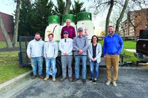
About the Author
Jim Anderson is connected with the University of Minnesota onsite wastewater treatment education program and is an emeritus professor in the university’s Department of Soil Water and Climate. Send him questions about septic system maintenance and operation by email to kim.peterson@colepublishing.com.
Continue reading for free