Six land developers wanted to build separate subdivisions right outside the city limits of Cave Springs, Ark. Initial plans called for each one to handle wastewater in his own subdivision, as the city had no wastewater treatment plant. However, government officials asked the developers to consider one large decentralized system.
Tom Bartlett, owner of Aqua Tech Systems LLC in Fayetteville, Ark., suggested a solution to the lead developer, Brett Hash, owner of Northwest Services LLC in Cave Springs. Bartlett’s proposal took more than three years to organize and involved two stages: a 92,400- gpd system called Fairway Valley Phase 1, and a 320,000-gpd system called City of Cave Springs Phase 2.
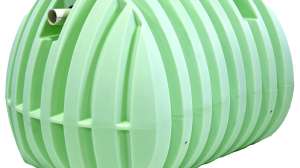
Fairway Valley, which treats water from 450 homes, became operational in January. It involves septic tank effluent pumping (STEP) tanks, a moving-bed biological reactor, submerged fixed-film aeration unit, and dripfield. Aqua Tech project manager Ken Gregory worked with the engineer to pull together the proprietary collection of equipment needed for the system supplied by Aqua Tech. When fully developed, the community will contain 1,495 homes.
Site conditions
Soils are sandy loam with loading rates of 0.18- to 0.345-gal/sf/day. The water table is 6 feet below grade. The topography is hilly and rocky, with limestone bedrock 4 feet beneath the topsoil. Filled with lakes, streams and caves, the area is home to many endangered species including the Ozark cavefish, gray bats, cave crayfish and bald eagles. A creek runs through the middle of the golf course.
System components
Daniel Lazenby of ESI Engineering in Springdale, Ark., designed the Fairway Valley system to handle 92,400 gpd. Its major components are:
• 1,250-gallon STEP systems
• 33,000-gallon equalization tank with two 30-gpm pumps and control panel
• Moving-bed biological reactor
• Submerged fixed-film aeration unit
• 15,000-gallon settling tank
• 15,000-gallon sludge-holding tank
• 25,000-gallon dosing tank with four 55-gpm/2-hp and two 85-gpm/3-hp turbine effluent pumps
• 1/2-inch pressure-compensated driplines on 2-foot centers with valves and headworks
• Four custom-designed control panels
System operation
Wastewater gravity-flows into the STEP tank, then is pumped to 2-, 4- or 6-inch force mains. To overcome the harsh terrain, the force mains run to a lift station, which pumps the sewage through a 10-inch interceptor trunk line to the 10- by 53-foot equalization tank. Pumps then send timed doses to the in-ground treatment plant.
“We’ll activate the Phase 2 plant when flows exceed the capacity of this system,” says Gregory. The second plant has two, 26-foot-diameter clarifiers in parallel after its two reactors.
Aerators in the stainless steel reactor chamber create turbulence that tumbles the sewage. This motion is the moving bed. Bacteria grow on free-floating, 1-inch-round plastic disks with honeycomb interiors that allow adequate scouring velocities and sloughing. “The chamber’s pretreatment capabilities knock BOD and TSS down by 50 to 60 percent,” says Gregory. “The moving bed also eliminates dead zones.”
Effluent gravity-flows to the submerged fixed-film chamber for further clarification. Microorganisms on the media digest more sludge, die and slough off. Fine air diffusers gently mix the liquor, enabling the sludge to settle. A sludge pump on the bottom of the tank moves the minimal sludge to the sludge-holding tank. Recirculation pumps running four minutes every hour send liquid rising from the sludge back to the equalization tank.
Clarified effluent in the fixed-film chamber rises to the top and rolls over a weir into a settling tank. “We need that tank to comply with our septic code, as it reduces the BOD and TSS from 30 mg/l to 15 mg/l,” says Gregory. Effluent gravity-flows to the dosing tank, then is pumped to the dripfield headworks. Retention time from entry to exit is four hours.
Dosing varies by field because of different loading rates. The Fairway Valley system (Dripfield 1) — the largest with four zones totaling 100,000 feet of tubing — lies under the golf course driving range. Dripfield 2 for Phase 2 has six zones, is 2,500 feet away from the treatment plant, and serves as part of a fairway.
Installation
Bartlett’s solution enabled developers to maximize their sites, building three homes per acre instead of 1.5. STEP tanks are installed as homes are built. “The slow occupancy rate means the microorganisms in the treatment plant take longer to establish themselves,” says Gregory. “However, as long as the effluent comes out less than 15/15 mg/l, the biology will build itself up as the flow increases.”
Utility Contractors in Wichita, Kan., installed the treatment plant and force mains. Moore Brothers Septic Systems Inc. in Lincoln, Ark., installed the drip lines and control panels, solenoid valves and pumps. Engineer Ferdi Fouri of PDC Inc. in Fayetteville oversaw the work.
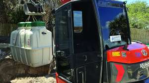
The site for the tanks and treatment plant was an 8-foot-deep sunken area from the main parking lot to the clubhouse. After excavating 4 feet to the limestone bedrock, Utility Contractors had the needed depth to set the 10-foot-diameter fiberglass tanks on 12-inch-deep gravel beds. They trenched out and poured the concrete deadmen in place for the tanks, poured the pads for the treatment plant, and installed the reactor and aeration units.
Once the piping was connected, they backfilled with pea gravel to the top of the tanks, mounded dirt around them, cut the 24-inch risers to grade, and secured the lids with inset square-head security screws. Moore Brothers mounted the outdoor NEMA 4X control panels on Unistruct stainless steel frames secured to concrete pedestals on bases. The panels, one for the dripfield and three for the treatment plant, have a touch screen and auto- dialer. The area was seeded with grass and a privacy fence erected.
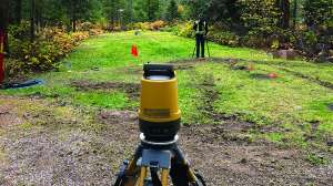
Using a backhoe, Moore Brothers dug an 18-inch-deep trench for the 2-inch PVC supply and return lines, laid out the header and return line, drilled the holes, and glued a saddle adapter to those lines every two feet. After a surveyor laid out where the first drip line went in each zone, the men buried the tubing 10 inches deep on 2-foot centers.
The tubing has an emitter every two feet. “We wanted the discharge to be level with the roots to irrigate the grass and enhance evapotranspiration or soaking into the ground,” says Gregory.
Dripfield 2 had a 4-inch supply line because of the distance traveled. The line also had to cross a 20-foot-wide creek. Moore Brothers put the pipe in a sleeve, then plowed a trench in the creek’s gravel bottom beneath the bridge. They ran the control lines for the zone valves through a conduit attached to the underside of the bridge. With the water behind, they used a 2-inch header and return lines.
“Twenty-four-volt DC didn’t want to travel 2,500 feet from the control panel, so we used a 120-volt power converter that trips for those zones, then converts back to 24-volt DC,” says Gregory. The golf course stayed open during the installation.
Maintenance
The City of Cave Springs hired a full-time Class 3 wastewater operator to conduct 45-minute, twice-weekly inspections. “The Phase 2 plant is huge and requires this level of training,” says Gregory.
After getting into the decentralized project, the developers decided not to become maintenance providers. They handed the system to the city as a thank you for letting them build their subdivisions. The system was paid for through a private bond issuance with Northwest Services LLC set up by Aqua Tech Systems LLC.
Continue reading for free