
Aerial images go a long way in this industry for design purposes, and layering those images with accurate topography maps showing detailed contours is essential.
Determining elevations during design and installation is critical to evaluating the direction of water movement and for the proper location and installation of components. Design plans should include a benchmark, which is a fixed point on the site plan designated at a comfortable distance from the construction area. This allows the installer to accurately set elevations for the installation.
Establishing a benchmark
Mean sea level is typically referenced for benchmarks on large projects and developments, but for most onsite wastewater treatment systems, benchmarks have assumed elevations that are not tied to any national or local datum.
All other elevations are then measured relative to that mark. The benchmark is identified, and its elevation is noted for field calculations for invert setup, tank and component setting, and general ground surface shaping.
Topographic details on a site plan include existing and proposed variations in elevation of the natural and constructed physical features. Contour lines connect points having the same elevation. The distance or interval between them varies depending on the scale of the plan and the slope of the landscape. For OWTS site plans, the contour line interval is normally 1 or 2 feet. A topographical evaluation should be done as part of the site review.
The starting point
The stub-out pipe elevation is typically very important when designing and laying out components because it is the controlling elevation for all down-gradient components. If the stub-out is at a lower elevation than is indicated on the design, all elevations in the system must be adjusted accordingly.
Many components are restricted in how much elevation can be changed because of limitations on burial depth. If the treatment train includes only gravity components, the vertical separation requirements for the soil treatment area must be met to ensure proper treatment. In this case, a stub-out elevation that is too low will require the addition of a dosing tank and a pump/siphon to maintain the required elevation in the STA.
If the design plans show a system cross section through the whole treatment train, each of the components is shown with inlet and outlet elevations, finished grade elevations and elevation of existing or proposed structures. The system profile also provides details for the installer related to slope requirements and separation distance to a limiting condition, such as the seasonal high groundwater table or a restrictive horizon.
Further information
The property lines, wells, proposed wells and other features requiring setbacks from the OWTS need to be verified, especially if any component is at or close to a setback requirement. Permanent markers set by a professional land surveyor and referenced on a design plan or survey plan provide the least liability to the installer in case of a property line or setback dispute.
All horizontal setbacks must be verified once the components are staked out. Critical distances to wells, wetlands, property lines and other strict jurisdictional setbacks need to be verified before installation can occur. If the components or the soil treatment area are in proximity to the setback, a professional land surveyor can be hired to set the location of the system. Verification of the location and all setback requirements must take place.
Surveying equipment and techniques
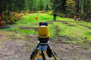
Determining differences in elevation of several locations using surveying equipment and transferring a benchmark requires skill and a working knowledge of the equipment. The quality and type of surveying equipment needed will vary depending on the user and the site. Installers often employ a laser level to transfer benchmarks a short distance (less than 200 feet). Laser levels are an indispensable tool to set elevations during construction. They are easy to use, and operation requires only one person.
A tripod with pointed legs, which needs to be secure in the soil to avoid movement, holds a level instrument in place. A laser level utilizes a rotating head that emits a horizontal beam in a plane at a constant elevation. A laser detector receiver is mounted on the leveling rod and slid up or down the rod to find the beam plane. As long as the installer has a line of sight to the laser level, then he or she can raise or lower the laser detector on the rod to detect the beam. A beeping or constant sound signals that the detector is close to the plane or even with it. Changes in elevation from one point to the next are determined by measuring the distance required to move the receiver along the rod.
A direct reading level rod is graduated in feet and tenths of feet. Some rods may be graduated similarly to a tape measure or common ruler with 12-inch markings. Fiberglass level rods extend to as much as 30 feet with telescoping sections. The graduated scale on the level rod is specifically marked to increase the likelihood of taking correct rod readings. Depending on the region or designer preference, the design plans may be marked with elevations in whole and fractional inches, not in tenths of an inch. In this case, the installer may need to convert the design elevations or rod readings.
In some cases, an installer may need to transfer a benchmark closer to the site area to make rod readings easier to obtain. When performing a benchmark transfer with a laser level, the instrument is placed in the line of sight of both the existing benchmark (BM1) and the transfer point (BM2). The laser level must be set higher in elevation than the benchmark and the transfer point.
Once the laser level is mounted on a tripod and leveled, the installer can then take the rod with the laser detector and place it on BM1. The laser beam is detected by sliding the detector up and down on the rod as needed. Once the laser beam is located, the rod reading is recorded for BM1. The height of the instrument (HI) is determined by adding the rod reading taken at BM1 to the elevation of BM1. The HI is the actual elevation of the laser beam plane. Once the HI is established, the installer can move the rod to BM2. A rod reading is taken and recorded for BM2. The elevation of BM2 is determined by subtracting the rod reading at BM2 from the HI. With a new benchmark established (BM2), the installer can now move the instrument to a more desirable location and proceed with setting up the elevation of major system components of the OWTS.
With detailed site plans, understanding benchmarks is critical to the installation of various components in an OWTS. Surveying equipment is essential during the installation process.
Continue reading for free