Jenni and David Belford, through their experiences with Adventures for Wish Kids, decided to build a year-round fun camp for children with serious illnesses. They broke ground for Flying Horse Farms in Mt. Gilead, Ohio, in fall 2009.
Aaron Heydinger, P.E., of Advanced Civil Design in Columbus, and Joe Keiser, P.E., of StreamKey in Cincinnati, designed the onsite treatment system. Dynahoe Construction and Excavating in Circleville won the bid. Superintendent Nick Mets oversaw the installation of the gravity-fed system with fixed activated sludge treatment (FAST) and pressure-dosed drainfield.
The project lasted six months. Half the time, Mets and his crew battled high water, trees and roots. The electrics, pumps, and controls took the remaining months. The camp opened in fall 2010.
Soils are heavy glacial till with percolation rates of 0.13 gallons per square foot per day within the top 6 inches. The water table is 24 inches below grade. The wooded drainfield area has a 3 to 15 percent slope.
Heydinger designed the system to handle 10,000 gpd. Major components include:
Wastewater gravity feeds through 10- and 12-inch PVC sewer mains to the lift station, then is pumped to the septic tank and flows through a Bull Run valve (American Manufacturing). When the camp is active, the valve is set to high flow, sending effluent by gravity through the primary treatment system. During the off season, the valve is set to low flow, sending liquid by gravity through the smaller ATU to the disposal tank.
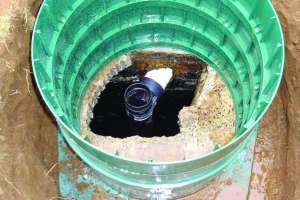
In the primary system, effluent flows from the septic tank to the equalization tank, then to the aeration tank in which six regenerative blowers send large volumes of air to six submerged aerators and mixing diffusers. A venturi in the aerators breaks the incoming airstream into smaller bubbles, producing a vacuum that pulls in surrounding liquids. The turbulent plume creates horizontal and vertical mixing patterns that handle 18 to 30 pounds per day BOD.
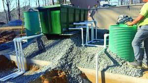
Effluent flows from the aeration tank to the larger ATU for further treatment. A boxlike container suspended from the lid contains media to which bacteria cling. Above ground under a poly box is the blower unit with a blower motor and air filter. The system reduces BOD and TSS to less than 30 mg/l with 65 percent nitrogen reduction.
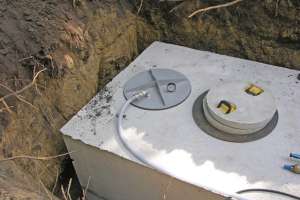
After 24 hours in both the aeration and ATU tanks, effluent flows to the dosing tank. The heavy load on the turbine pumps makes them run warm. To prevent overheating, the pumps sit inside laminar flow collars — lengths of 1/8-inch PVC pipe with three rows of 3/4-inch holes near the top. When the pumps activate, they draw liquid up through the holes to cool the pump jackets.
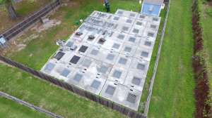
The pumps cycle 24 times per day, sending 1,200 to 1,500 gallons through the hydraulic rack to the drainfield. The 12 zones, each with 16 laterals 150 feet long on 6-inch centers, are dosed sequentially via an electric valve opened by the control panel. The 1/8-inch emitters in the drip tubing operate at 10 to 60 psi. The return line from the drainfield backflushes components and drains into the dose tank.
The only suitable soils for the drainfield lay 1,570 feet beyond the dosing tank in a densely populated wooded area. While four inches of snow covered the frozen ground, Mets’ crew cut trees with 6-inch trunks or smaller and cleared the undergrowth. Bobcat excavators moved debris to a chipper. The machinery did not compact or damage the soil.
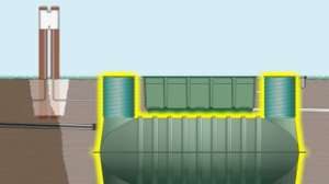
The crew returned in late April to excavate the 130- by 35-foot trench for the lift station and primary tanks set in series. The low-flow ATU tank abutted the equalization tank. The deeper the crew dug, the higher the water rose. Mets deployed a 12-inch diesel pump, then several 2- and 3-inch gasoline pumps, but could not get ahead of the flow.
“We turned off the pumps and let the water seek its own level,” says Mets. “Once it had, we shot an elevation, took it to Aaron, and he calculated raising the tanks 18 inches to avoid flotation.”
The men also daylighted to a nearby waterway, an 18-inch bleeder line with 8-inch finger drains encircling the trench. The line, combined with the pumps, kept the area dry enough to enable work. Workers backfilled the trench with 5 to 6 feet of soil to bring it to its new grade, then added 6 to 8 inches of gravel to bed the tanks.
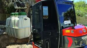
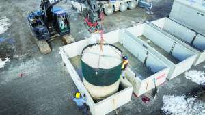
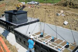
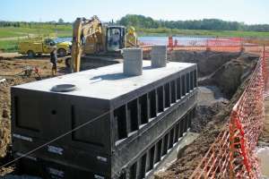
Nine semi-trailers delivered the precast sections. The three-piece 20,000-gallon tanks were each 30 by 12 by 11 feet and weighed 42,000 pounds. “We set all the tanks in two 12-hour days with a 250-ton crane, piping as we went,” says Mets. The tanks were quickly backfilled with stone almost to the top seam and topped off with soil.
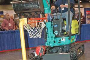
Before beginning on the drainfield, the crew cleared the remaining brush from the area with compact loaders on rubber tracks. “The grade and contours made installing the tubing very difficult,” says Mets. “The vibratory cable plow has a 35 hp diesel engine, but we had to pull it with a mini-excavator to manage the slopes.”
The workers precut the tubing for each run, hooked one end to the plow, and left the remainder coiled on the ground. A sentinel continually monitored the coil and sounded the alarm when the plow kept moving but the tubing stopped. Roots snagged the lines, ripping them in half or stretching them beyond usage.
Besides being limited by the contours and elevations, the crew tried to stay four to six feet away from the bases of trees. The tubing went six inches deep in some locations and lay on the ground in others. “It took five weeks to install the drainfield, averaging about 1,000 feet per day,” says Mets.
StreamKey trained the camp’s maintenance supervisor to check the system daily. For two years, a StreamKey technician will do standard maintenance three times per year. Then the owners must sign a service contract with a provider of their choice.
Continue reading for free