For those reading this series on the Treatment Train for the first time, welcome to the process of evaluating the components of an onsite wastewater treatment system.
In our last discussion, we added a pump to the system. This segment on system controls takes us to a new level of understanding. Controls can range from old-school piggyback units to sophisticated computer-controlled technologies. So, buckle up: The Treatment Train just became high-speed.
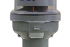
Let’s start with the most basic control — the piggyback, where a plug interceptor wired with a mechanical float plugs in between the prewired pump and the wall receptacle. Simple, yes, but these were designed for basement sump pumps and cannot withstand the corrosive environment in a pump tank.
There are four basic factors in a control system: the environment to be controlled, a sensor of some sort, a controller that receives the sensor signal, and the device that is controlled — such as a pump, valve, air blower, or alarm.
In the rest of this series, we will reference the different environments we’ll be controlling. Our last article covered a pump-to-gravity system, which includes a pump tank in which liquid levels change due to flow from the source through the septic tank.
In this case, when the liquid level in the pump tank rises, a sensor responds and sends a signal for the pump to turn on and pump out a specified volume of liquid (the dose). If the liquid level does not drop and continues to rise, a second sensor activates an alarm, indicating a problem.
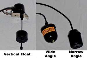
Now we’ll talk a bit more about sensors. Mechanical floats have been used for decades as a standard method of liquid-level control. The basic mechanical float has an internal ball that travels in a cage, activating a microswitch. Some mechanical floats can carry a specified load (electric current) that can directly activate devices such as pumps. Others are low-voltage and are intended only to transmit a signal that activates an electrical contactor in a control panel.
Another characteristic of floats is the angle of operation. Many mechanical floats are considered wide angle, as even in their finest adjustment they need to be raised as much as three inches to activate. Other more sensitive signal floats, such as mercury units, are often called narrow angle, as even a 1/4-inch movement will cause activation.
Narrow-angle floats are typically used in timer applications. That’s because if used for direct operation, even the slightest turbulence in the liquid surface can trigger the float to send a sporadic signal, causing chattering and eventual burnout of the controlled device. It is important to know what type of float is specified for the system, as installing an improper float can lead to expensive repairs.
Most floats are connected by an electrical cord. In the case of mechanical floats, the cord length from the mounting point (tether) can be adjusted to control the dose. When corded signal floats are used, the tether length is typically set at about three inches.
Vertical mechanical floats have a cylindrical float that travels on a vertical shaft, engaging a load-carrying microswitch. These floats can be fairly narrowly adjusted and are often used in the internal pump basin of single-pass media filters.
There are many options for mounting sensors in the system, but whatever method we choose, we must consider ease of removal for inspection and service.
Now let’s talk about other kinds of sensors. The onsite industry is beginning to see methods of liquid-level control that have been applied to other industries for decades. A single pressure transducer can monitor the rise of liquid by trapping an air pocket in a bell-shaped housing. This type of sensor can activate numerous devices as pressure increases in the bell. These sensors are typically paired with proprietary control panels.
Another tried-and-true liquid-level control device is a conductive sensor, in which a rising liquid level provides conductivity between electrodes, thus transmitting low-voltage signals to a compatible control panel.
In addition, some larger systems employ ultrasonic sensing devices that transmit a sound wave from the sensor to the liquid surface and back, constantly communicating with a control system to activate devices such as pumps and valves.
Later in this series, we will discuss the use of light-intensity meters and photo sensors in the operation of disinfection devices.
One important note here about any electrical component: The wire connections must be properly sealed and protected from corrosion. We can do this by using silicon- or grease-filled wire nuts within internal or external splice boxes, or by running the factory-sealed sensor cords through conduits to the control panel. In running sensor wires, it is important to seal the conduit passages with electrician’s putty to prevent corrosive gases from migrating from the controlled environment into the panel circuitry.
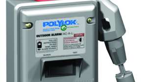
Control panels come in many sizes and configurations. While simpler systems might employ demand dosing, more complex systems rely on timed dosing. In any case, certain features are invaluable in all control panels. These include:
• Dedicated internal electrical breakers.
• Hand/Off/Automatic (HOA) control switch.
• Data loggers including event counters (also called cycle counters).
• Running-time clock (also called an elapsed-time meter).
From the most basic to complex, these features enable comprehensive management of any system. Some may question the inclusion of dedicated electrical breakers, so let me address that with a question: If we have a control panel servicing a pump and alarm system, and this panel has a single 30-amp electrical breaker from the structure’s subpanel to the control system, and if for some reason the pump fails and trips the breaker, what happens to the alarm? It loses power, and we don’t know of a problem until wastewater either backs up in the structure or comes out of the ground.
Test switches (HOA) are extremely valuable when performing O&M on a system, as they make it possible to turn the pump on and off as needed, or to verify its automatic operation in a test scenario.
As for data loggers, comparing the number of times a pump is activated to how long it has run enables us to determine exactly how much effluent was pumped and at what rate. Both figures are extremely valuable in determining if a system is being used according to design.
As management will soon become the norm, learning to use these tools for reporting will be very important for qualified service providers. Other valuable management tools being used in our industry include programmable logic controllers (PLCs) that can be adjusted to control unit processes such as recirculating media filters, time-sequenced aerobic treatment units and timed dosing of disinfection devices and soil treatment units.
In addition, telemetry devices on the market enable remote monitoring and adjustment of systems from an office-based computer or handheld smart phone.
Let’s quickly review the key points about onsite system controls. We need to ask:
• What environment in the system are we trying to control? Liquid level? Oxygen level? Application rate?
• What kinds of sensors are used in the system? Mechanical floats? Signal floats? Pressure transducer? Conductive electrode?
• Are the sensors load-carrying or low-voltage transmitters?
• Does the sensor mounting facilitate easy removal, inspection and service?
• Are the wiring connections and conduits sealed to prevent corrosion?
• Is the alarm component in the control panel wired independent of the pump?
• Is there a test switch in the control panel to facilitate O&M?
• Are there data loggers to provide important management information?
• Is the system equipped with telemetry? If so, are you trained to manage it?
To learn more about operation and maintenance of control systems and all the variables only touched on in this article, check this magazine’s events calendar or visit www.nawt.org for an O&M training session near you.
Our next installment of O&M Matters will discuss media filters as final treatment and dispersal components. If any terms used in this article are new to you, check out the glossary of terms at www.onsiteconsortium.org/proj.html# glossary.
About the author
Kit Rosefield is an adjunct instructor at Columbia Community College and a trainer for NAWT and the California Onsite Wastewater Association. His company, Onsite Wastewater Management in Mi Wuk Village, Calif., has a consumer education service at www.septicguy.com. Reach him at 209/ 770-6760 or kit@septicguy.com.
Continue reading for free