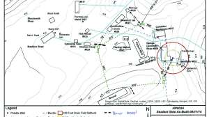
Flow equalization is a design and management concept that can help reduce stress on system performance due to high peak flows. In flow equalization; the peak flows are stored for a period of time to be delivered to downstream components, including the soil treatment unit, over a longer period of time.
Flow equalization systems are more commonly found in systems with advanced pretreatment and in facilities with variations in flows, which are found in many commercial systems. With commercial systems, the septic tanks are still sized based on the peak flow, but the downstream components can be sized based on the equalized flow, allowing for more appropriate sizing of advanced treated effluent and soil treatment areas. For many jobs this will result in a cost savings that far exceeds the cost of a larger dosing tank and control panel.
Residentially, it is common for the flow over one day to be equalized over 24 hours, but it can be done for longer periods, especially if peak flows last longer than one full day such as with commercial properties. For this to be accomplished, the tank must be large enough to handle these flows, and a timer instead of a float should control the pump operation.
The pump tank capacity for a single-family residence using flow equalization is a minimum of 1,000 gallons or two times the daily design flow, whichever is largest. Commercial systems must calculate two values to determine storage requirements, design flow and required storage (plus a 20% safety factor). The sum of these values is used to determine the required capacity. To use these values, real flow data (daily flow values) is necessary for the system’s design. The average flow is the calculated average for the daily flow reading for a certain time period. Typically, 45-90 days of data will give a clear idea of the use at the site. Regular events should be factored into the flow equalization design. Annual events can be handled using other flow control methods, such as portable toilets or pumping. The storage is calculated as the sum of the flows above the average that needs to be held in the system.
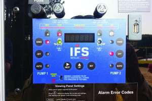
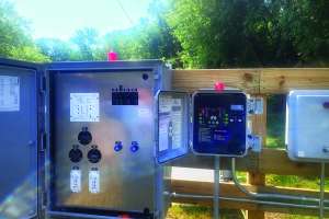
Flow equalization systems must have a control panel. The control panel can be quite simple or more complex based on the functions it must perform. Electrical components in the panel respond to water level sensors in the tank. The sensors are adjustable, and each is set to operate specific components in the tank. The sensors trigger the operation of system components to:
A single sensor may trigger multiple dosing functions. Examples of combinations triggered by a single sensor include, but are not limited to:
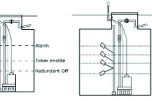
Many different configurations are possible in timed dosing. The figure illustrates the inclusion of a separate redundant off-float. When this float is in the off position (indicating a low effluent level in the tank), it protects the pump by not allowing it to operate, regardless of the pumping schedule set on the timer. “Timer enable” and “redundant off” functions may be controlled by the same float.
The illustration shows a configuration with a peak enable float installed between the timer enable float and the alarm float. When activated during high-flow events, a peak enable float shortens the rest period between normal doses. As a result, more dosing events occur each day and reduce the effluent level in the tank more quickly. “Peak enable” and alarm function may be controlled by a single float. Note that systems that include peak enable floats must be set so that forward flow does not exceed the capacity of the next component or the design flow of the system. Again, a cycle counter should be included to track the number of times the peak enable float is activated.
If a timer override float is included, it essentially (and temporarily) changes the system’s function to a demand-dosed regime until the effluent in the tank is reduced to a normal operating level. Using an override float can defeat the purpose of the timer system, but it may prevent the backup of wastewater into the residence. Certainly, a counter must be included to track how often a timer override float is activated. Once the system is in use, the counter will track how often the system is hydraulically overloaded.
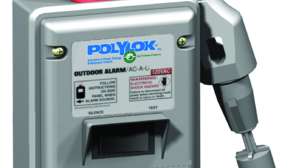
An alarm float should always be included in a float configuration. The alarm should consist of an audible device and an easily visible light. It should be wired on an electrical circuit separate from the pump. If the mutual circuit trips, the alarm will not function. Including a counter in the panel allows for the tracking of alarm events.
1. The pump OFF elevation must be set to ensure pump submergence.
2. The dose volume will need to be determined based on the design flow, requirements of the advanced treatment system, and regulatory requirements. A drawdown test must be performed to determine the actual PDR of the system, and it should not be taken from a design or pump curve but validated in the field. For new installations, clean water must be put into the dose tank to calibrate the pump, and the gallons per inch or dimensions of the tank are needed. The drawdown should be measured. The drawdown can be measured from when the pump activates to the moment the pump ceases. The PDR can then be calculated using this equation:
PDR = inches of drawdown x gallons per inch of the tank ÷ minutes in operation
Then the timer setting can be determined by the pump run time and its pump delivery rate (PDR):
Timer ON = PDR (gpm) ÷ dose volume (DV)
Timer OFF = 1440 minutes in a day ÷ by likely or typical doses per day and subtract the Timer On.
This will establish the amount of time between doses in minutes. This time may need to be adjusted over time if current usage per day is unknown.
You will need to enter the ON and OFF cycle settings in the panel. The technique for doing this varies by panel manufacturer.
3. If there is a timer-enabled float, the setting is determined by the projected flow from the system, the tank geometry, and the requirements of the succeeding component.
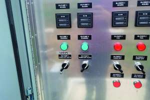
4. The alarm float is typically set at 90% of the total dosing tank depth. Verify that the alarm test switch activates both the audible and visible alarms. If there is a control switch (hand-off-auto), verify that it operates correctly in all positions. After a startup, the switch should be left in the auto position.
Ensure that the panel is watertight and that all openings are properly sealed (both in the panel and in the tank riser) to prevent moisture and corrosive gases from entering. All panel enclosures should be NEMA 4X rated (watertight, moisture-tight, and corrosion-resistant, among other requirements).
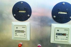
Confirm that an elapsed time meter and cycle counters are present and operate when the pump is activated. (Note that water is required for this.) Record the current meter and cycle readings found during startup. These records will serve as baseline data for the systems service provider.
Continue reading for free