A college preparatory school in South Kent, Conn., was expanding and needed a larger onsite system.
Officials hired Mark Lancor, P.E., principal engineer at DYMAR Corp. in Southbury, Conn., to design a conventional system that met the state Department of Energy and Environmental Protection discharge limits. Leggett, Brashears & Graham, a hydro-geological consultant in Shelton, Conn., used the MOD-Flow three-dimensional finite-difference groundwater model to calibrate hydrologic flow.
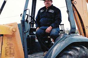
The project went out to bid based on components. Mark Green, manager of HLC Excavation and Tank Removal in Woodbury, Conn., won the contract to install the dose tank and drainfield. Unsuitable soils, logistics, high groundwater and bad weather stretched a two-month installation from September through early March.
Soils are sand and gravel with 6- to 8-inch cobble and permeability rates of 2.5 to 28 feet per day. The water table is 8 to 9.5 feet below grade. The drainfield is sited by a pond, wetlands and a road.
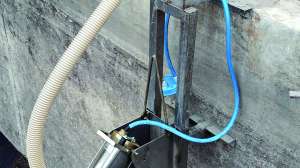
Wastewater flows from numerous buildings and pretreatment septic tanks through 6- and 3-inch force mains to the dose tank. Alternating on-demand pumps run 15 minutes, sending 1,528 gallons at 46 feet total dynamic head to the metering vault. (During high flows, two pumps run simultaneously.) Two 3-inch force mains carry the metered flow to the splitter vault, which alternately doses each zone’s distribution box with 5,000 gallons per cycle.
In the vault, flow A splits four ways: A 2-inch force main feeds paired drainfields 1-2, a 1.5-inch pipe feeds drainfields 3-4 and 5, and a 2-inch line feeds drainfields 6-7. Flow B splits three ways: A 1.5-inch force main feeds drainfield 8, a 2-inch pipe feeds drainfield 9 and a 2.5-inch line feeds drainfield 10.
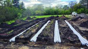
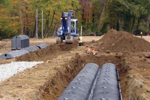
The drainfield has eight zones of seven laterals, either 68.75, 75, or 87 feet long. Approximately 240 feet of additional chambers drain stormwater from the soccer field.
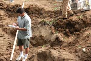
Green, two machine operators, and a laborer stripped and stockpiled 4,100 cubic yards of topsoil from the drainfield area, then brought in a screener and front-end loader to screen the material. “We had topsoil pushed into little mountains all over the east side of the site,” says Green. “Then we had to find enough room to stockpile the screenings and tailings.”
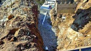
Using a Komatsu PC 128 excavator to dig 72-inch-wide trenches 2 to 4 feet deep, the crew quickly encountered an unending supply of cobble that they dug out, stockpiled and screened to an acceptable backfill material. The fact that the trenches required no bedding presented another challenge.
“It was tough to keep the trenches tight, find enough fine gravel for a level base and maintain elevations,” says Green, who constantly checked grades with a laser rod and LL500 laser level (Spectra Precision). “We often had to over-excavate to extract the cobble, then go back two feet and re-establish the subgrade with finer material. We did that for 4,329 feet, which is a lot of digging for four people, but I had no room for a second crew.”
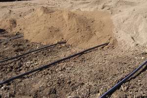
Trenching advanced 300 feet per day. After the team installed two rows of 96- by 36- by 12.5-inch-high chambers, they covered them with No. 410 nonwoven filter fabric (CULTEC) and backfilled to the crowns with 1.25-inch stone. Then they returned with the screener to sift the excavated material, covered the stone with 6 inches of it, and finished with 6 inches or more of topsoil to grade. Tailings were deposited along stream banks or other areas needing fill.
To avoid trapping themselves in a corner, the crew installed one zone at a time working west to east, then used the completed zone as a platform to install its neighbor. The Komatsu excavator, rated up to 30,000 pounds, safely tracked over the H10-rated chambers. “It was like working on a jigsaw puzzle,” says Green.
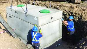
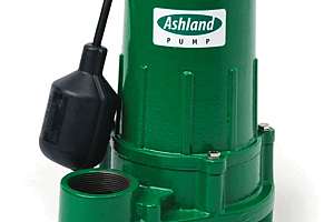
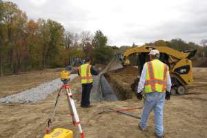
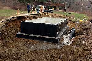
The excavation for the 14- by 20- by 10-feet-high pump tank was across a road from four residences, 5 feet from a heavily flowing stream on the other side and 10 feet below the water table. The crew quickly encountered severe water conditions. Green called groundwater specialists Dauti Masonry in Prospect, Conn., to help install a wet well and two 1/3-hp submersible pumps running continually to dewater the 40- by 40- by 14-feet-deep excavation.
“We benched and excavated more than 1,000 cubic yards of material by running an Hitachi EX200 excavator and dump truck 10 hours per day,” says Green. “As fast as the material came out, we stabilized the banks with stone.” The excavation required 85 tons of compacted 1.25-inch stone 6 to 8 inches deep.
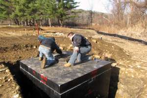
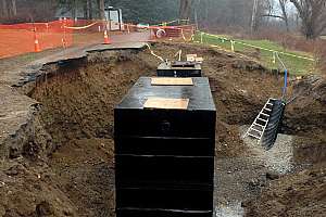
A trucking company brought the tank in four sections, and A-Quick Pick Crane and Rigging set them. The bottom section alone weighed 18 tons. Once the joints were solvent-welded together, Green’s crew wrapped the sides of the tank in urethane sheets and sealed them with propane torches. They sealed the inlets and outlets with waterproofing grout (Five Star Products), then tested the tank for watertightness.
Green also installed the splitter vault 700 feet from the metering vault, and used 50 psi hydraulic pressure to test the force mains going to the drainfield. The normal pressure is 37 psi.
Heavy rains stopped work in October, the soil froze two feet deep in December, a blizzard buried the site in January and the project finally resumed in mid-February. The system went operational in early March.
Waste & Water Equipment of Cromwell, Conn., installed the control panel and maintains the system.
Continue reading for free