Friction loss is the reduction in pressure of liquid flowing through pipe and associated devices as a result of contact between the liquid and the pipe walls, valves and fittings. The loss varies with flow rate and pipe diameter and the values presented in codes and manuals are estimated using the Hazen-Williams equation:
Friction Loss = 10.46L x (Q/C)1.852 / D4.871
Where:
L = length of pipe (feet; include addition of equivalent lengths for fittings)
Q = flow rate (gpm)
D = actual pipe inner diameter (inches)
C = friction coefficient
The friction factor - C) is a unitless value that is dependent of the pipe’s inner surface’s roughness.
The lower the value of C, the greater the friction loss. Values for the friction factor for PVC pipe range from 130 to 150. For new pipes, 150 is often used and 130 may more accurately represent aging pipes that have built up material over time. The smaller the pipe diameter and the greater the flow rate, the more friction loss in a given length of pipe. In pressure applications, when smaller diameter pipes are used, there will be more energy lost to friction in the pipe, which requires more total dynamic head from the pump to overcome the friction loss.
Friction Loss Example:
What is the friction loss generated by liquid flowing at 32 gpm through 100 feet of 1 1/2 inch Schedule 40 PVC, assuming C = 130?
Friction loss (ft) = 10.46 x 100 x (32/130)1.852 / (1.54.871)
= 1046 x (0.2461.855) / 7.21
= 1046 x .075 / 7.21
= 10.8 ft of friction loss
Many resources do this math for you and provide table values of friction loss. Note that these tables often provide the friction loss per 100 feet, so the length of the pipe must first be divided by 100 before being multiplied by the factor given.
The other issue with the friction loss in pipes is fittings. All fittings increase the friction in a hydraulic system due to the added roughness in the transitions. The number and types of fittings can impact the required pump size.
Tables online or in manuals provide the equivalent pipe length for various fittings and valves. The equivalent pipe lengths are an indication of the friction that various pipe fittings can produce. These lengths are added into the length of pipe from the tank to the point of delivery. For example, if the friction loss we calculate above in the 1.5-inch pipe had two 90-degree standard elbows which add 8.6 feet of equivalent pipe, result in a total of 108.6 feet of pipe with a total friction loss estimate of 11.8 feet.

Low Pressure Pipe Distribution
With pressure distribution, effluent is delivered either to taps in a pressure manifold (pressure-dosed gravity systems) or to multiple points across an infiltrative surface with LPP or drip distribution. By definition, pressure distribution systems incorporate a pump or siphon to provide the energy needed to overcome the forces of gravity. Pressure distribution systems using pumps can be dosed either on demand or at specific times. Those with siphons are inherently demand-dosed. Use of a siphon is limited to sites where the soil treatment area is downhill from the siphon tank, but systems can still be pressurized because of the energy they provide. Effluent can thus be distributed along the entire length of an infiltrative surface without using electricity.
Pressure distribution substitutes for the biomat in gravity systems to distribute effluent uniformly across the infiltrative surface. It provides increased treatment efficiency on sites with soil and size limitations and promotes soil treatment performance by maintaining vertical unsaturated flow and also may reduce the degree of clogging in finer-textured soils. Pressure distribution closely approaches uniform distribution.
One often overlooked benefit of pressure distribution is that it ensures resting periods between applications, allowing time for the soil or media to recover. Designs should allow for a number of resting periods. A typical residential pressure distribution system is designed with four dosing and resting periods per day. Equally spaced applications allow resting between doses and more uniform application, resulting in more consistent oxygen transfer and better treatment potential.
A timer can further assist in spreading out the application of effluent. Typical demand dosing, by comparison, which turns the pump on whenever sufficient effluent is available. Another benefit of pressure distribution systems in cold climates is the draining of effluent and the soil quickly after a dose to limit slow moving and ponding effluent which is more likely to freeze.
Pipe Sizing and Its Effects
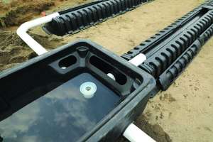
The pipe diameter, orifice diameter and orifice spacing must be determined for each LPP system. As the lateral diameter increases, the maximum allowable length increases, but as lateral diameter decreases, the velocity in the pipe increases. Increased velocity is a benefit, as it helps keep solids suspended. The length of the laterals is related to the number and size of the orifices.
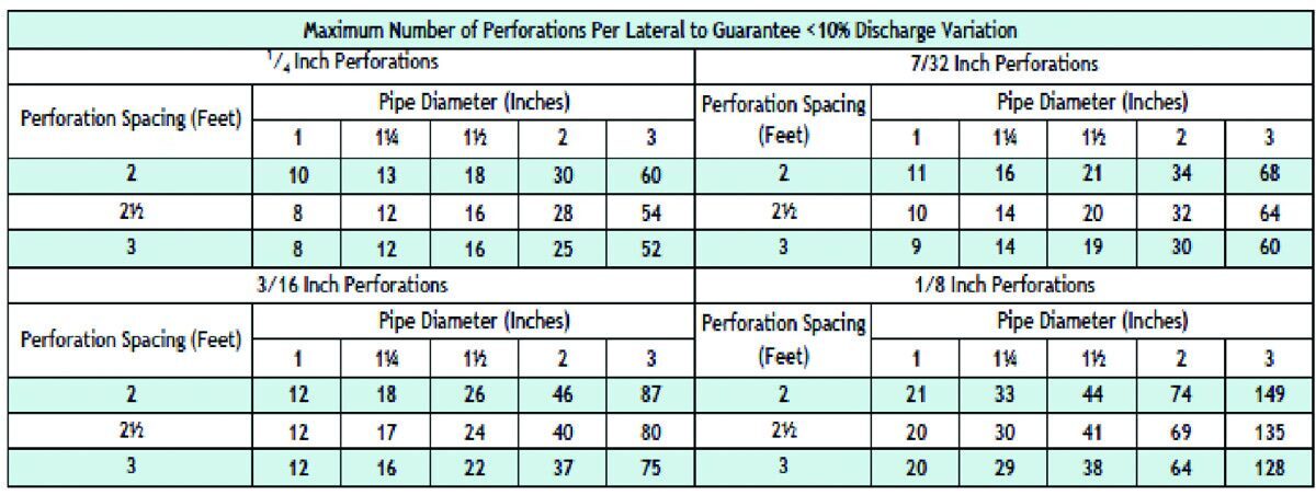
A general rule of thumb/rule requirement for low pressure pipe distribution is that the discharge from each orifice must be within 10% of the others. When pipes have multiple outlets, they have a F factor based on the number of perforations. By using the F factor for pipes with multiple outlets, the friction loss is calculated as if the entire flow were moving through the entire pipe. To assure the discharge is within 10%, the friction loss in the pipe should not be greater than 20% of the average operating pressure head.
By using a friction factor and the friction loss for plastic pipe, tables have been made with the number of perforations allowed based on the pipe diameter and size of perforation. An example of this table is shown from our University of Minnesota Design Forms is shown below (septic.umn.edu/forms-worksheets/).
Friction loss in pipe is a critical aspect of septic system design that must be considered to ensure the proper pump or siphon is chosen and even distribution is achieved.
Continue reading for free