Sometimes, one soil treatment area just isn’t going to cut it.
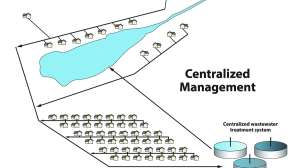
There are many situations when designers may choose to design multiple zones for an STA or may want to split after flow equalization to pretreatment systems. This can occur with single-family homes and even more commonly in commercial or cluster systems.
This is done to build in the ability to periodically rest parts of the system, or it may be required by the system design to minimize pumps or the size of the pumps.
Application-dependent
Gravity - Alternating/Diversion Valves - These valves manually direct flow from one component to another. Diversion valves can be utilized in gravity distribution systems to switch between beds or trenches. Typically, these are a gate or ball valve.
In gravity systems, D-box outlets or drop boxes can be capped or opened and closed with a ball valve. Manual alternating valves (a single diversion valve or a pipe assembly) allows dosing and resting cycles for zones with the goal of one zone being in operation at a time.
Pressure Indexing/Switching Valves - These are used to dose multiple components one at a time. Switching valves are often referred to as indexing sequencing valves because they automatically direct flow to two or more final treatment and dispersal components, one or more at a time, and in a prescribed order.
Indexing valves use a different outlet at each succeeding cycle, so at every cycle the pressure from the pump “switches” to another outlet and is ready for the next cycle. They have one inlet and two to six outlets. Zone valves can be used mechanically, sequentially diverting the flow of fluid to multiple zones within a soil treatment area.
Be cautious when designing multiple indexing valves on a slope as they will drain to the one at the lowest elevation. In general, using multiple indexing valves in series is not recommended.
Unpacking pressure valves
With pressure distribution, some technologies require multiple zones to overcome physical constraints of available pumps. This can be done with dual alternating pumps, but this function can also be achieved with a valve. In pressure systems, valves may be a hydraulic or electrical mechanical valve.
Hydraulic mechanical valves use water pressure to sequentially dose zones. Hydraulic switching valves switch to the next zone at the initiation of a dose. There is a risk of malfunction where it will not rotate to the next zone. The challenge is that that problem is typically not identified until there is a service visit or a visible malfunction.
Electrical mechanical ball valves use an electrically activated motor to open and close ball valves. These automated valves do require power to turn the valve open, but do not require power to hold position like solenoid valves. Ball valves work well in situations that involve large volumes of flow and are less prone to clogging. These valves are tied to a control panel and have the ability for remote monitoring.
Both hydraulic and electrical ball valves require a pressure relief valve to function correctly. Air relief valves are designed to release excess pressure in a system, allowing the valves to actuate and alternate as the design recommends. Air relief valves should be installed on the force main. Placement as recommended ensures proper operation and prevents issues like valve cycling or skipping zones.
Another option
Solenoid valves can also be used to perform an alternating function. Solenoid valves use an electrically activated coil to turn on and shut off the solenoid valve to alternate zones.
In a valve system, the solenoid raises a plunger that opens a downstream drain which reduces the water pressure above the diaphragm resulting in the opening of the normally closed flow path through the valve body. In its resting state, a solenoid valve is closed with a plunger blocking the orifice to the downstream drain. To open the valve, a simple electric current runs through the solenoid and creates a magnetic field. This magnetic field lifts the plunger, which opens the downstream drain and thus opens the valve.
Each zone or treatment unit has a designated solenoid valve to control flow. A control panel is needed to sequentially energize the solenoid valves to deliver a dose volume to the components.
Solenoid valves have smaller orifices which limit the flow rate and may make them inappropriate for larger low-pressure distribution. The valve body size determines the flow path size, therefore larger valves equate to greater flow. They do not require a pressure relief valve as pressure is released through the solenoid where under low-pressure conditions, a spring presses down on the diaphragm, closing the valve.
Typically, OWTS do not use pressure regulating solenoid valves. When needed, this is done with a separate pressure regulating valve located in the piping network to adjust the pressure.
Design considerations
When designing an automated valve, it is critical to understand the impacts of wastewater on mechanisms within the value. They perform their best with clear water and will have increasing maintenance needs as the wastewater becomes dirtier.
With well-settled residential wastewater, they may perform adequately, but it should be noted that they are best suited for wastewater meeting secondary treatment or better in relation to reduction of solids. With commercial applications, valves should be avoided, or adequate pretreatment designed to ensure treated effluent is being distributed by the valve.
Installation keys
Manufacturer installation protocols should be followed.
Ensure appropriate bedding material is used for the valve. To provide a stable base, the valve should be placed on native soil or a compacted foundation to limit movement after installation.
To assist in operation and maintenance, the valve should be placed inside a valve box that comes at least to grade and the box must be stabilized. Housing that encloses an operating component or device and extends to the ground surface, allows access for component inspection and operation verification.
Pressure indexing/switching valves hold liquid in the legs of the valve, so insulation of the enclosure lid is important to avoid freezing. Foam packing peanuts or some other insulation material can also be placed in a heavy-duty plastic bag and used around the valve. Six inches of washed rock for storage of water under the valve box is recommended.
It is important to keep this valve close to the pump.
The valve should be located in a high spot in the piping so that it can operate properly. The pipes should be able to drain following a dose.
Take care that soil and PVC shaving do not get into valves by using a PVC cutter versus a saw as they will collect in the valve.
Operation and maintenance
It is critical to check the function of valves on a regular basis. In gravity applications, the service provider should record which laterals are in operation and adjust as required in the design. Check that this has not been changed by the owner during the service interval.
With indexing/switching valves during operations and maintenance, the service provider should verify operation by observing whether zones are dosed sequentially when they initiate a series of manual doses. If clogged, they do not rotate to the next zone. This often happens with septic tank effluent. Maintenance for this typically involves taking them apart, cleaning the internal components and reassembling.
The schedule for maintenance is dependent on use and the effluent quality. The service provider should note any maintenance that was performed on the switching or sequencing valve. Dirt and debris, flow and pressure, coil burn-out (solenoids), power supply and damaged seals/assembly are all items to evaluate when troubleshooting.
Continue reading for free